|
Modeling 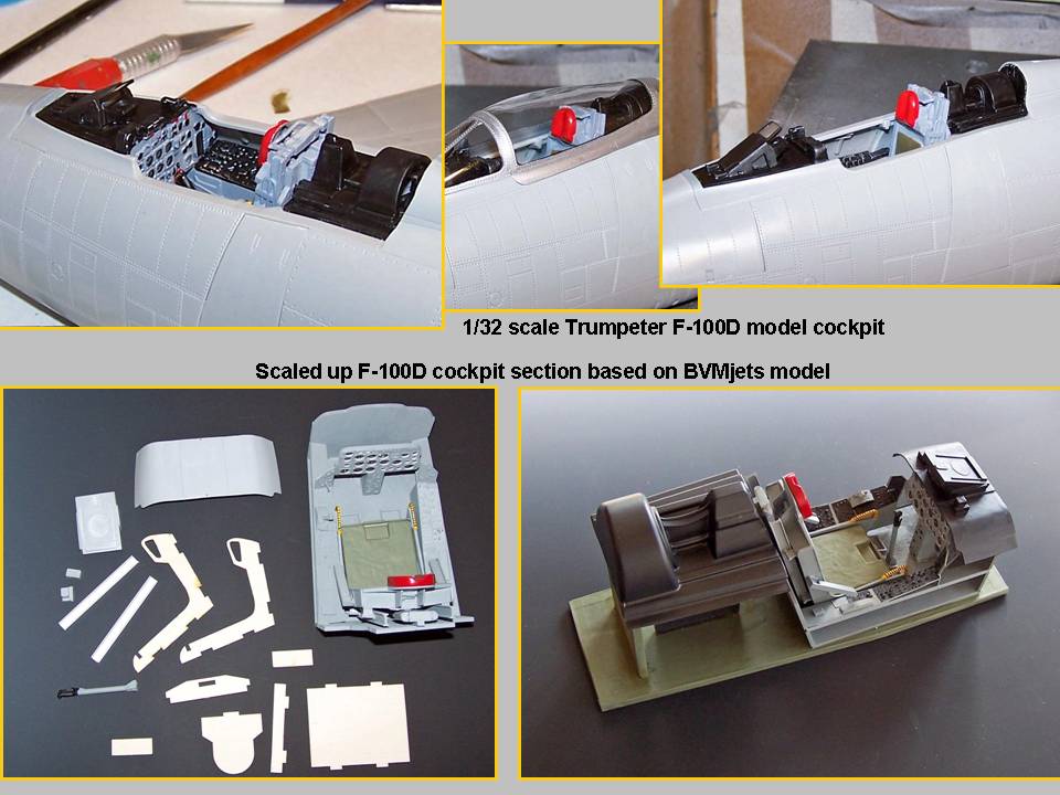 |
First tub sections 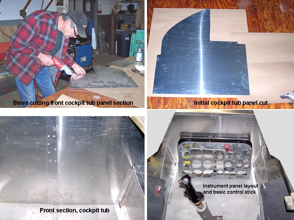 |
New instrument panel 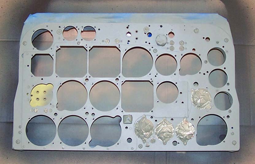 |
Making the cockpit presented a really tough challenge. First, the work space is limited, so working inside the cockpit "tub" often required a "scrunched up" position -- hard on the knees and back. Second, the number of items to be manufactured is daunting. Third, detailed documentation and pictures are hard to find.
Fortunately, I did have one really big advantage ... I found and bought a cockpit simulator. Therefore, I had a good template to work from. The simulator section was far from complete, but it did contain the essentials that made it useful as a cockpit procedures simulator. Most important, the ejection seat was at least usable as a base. (As we discovered, the ejection seat was not meant to be ejected -- several stencils indicated that it was meant "FOR TRAINING ONLY" and removing the ejection seat from the simulator turned out to be a three-day job that included cutting some heavy retaining plates.) There were, of course, no side instrument panels, no center pedestal, no rudder pedals, and so on. Never mind all that ... we had a great starting position that gave us accurate measurements for the major cockpit components.
The first job was to build some models. The "Flight Manual for the F-100 Super Sabre" contained many excellent drawings, so that was a good place to start. The Trumpeter company's 1/32-scale F-100D had an excellent cockpit that served the purpose of getting a "3-D" feel for the basic cockpit layout. The 1/32-scale cockpit is shown in the top three pictures in Figure 1, cell 01. The 1/8-scale BVMjets cockpit is large enough to scale up easily. As you can tell by looking at the bottom two pictures in Figure 1, cell 01, the BVMjets model cockpit is made of several different materials, including plywood, plastic, and fiberglass. (If you want to own and fly a truly superb -- and BIG -- F-100 model with a real jet engine, take a look at the www.bvmjets.com website to order your kit!)
After getting a good "feel" for the cockpit layout through the modeling work, I traced the major components on the aluminum sheet. Figure 1, cell 02, shows Steve cutting the first cockpit tub panel, the completed panel, and the completed bottom front section of the cockpit tub. The lower right-hand corner of the picture shows the basic tub layout ... and the new instrument panel frame that will become the base for the flight- and engine-instrument installation.
Note: You can enlarge the pictures by clicking on them. Then maximize the window to get an even closer look.
|
Modeling |
First tub sections |
New instrument panel |
As you examine the picture in the lower right-hand corner of cell 02 in Figure 1, note that I have simply "parked" my newly-constructed panel in a safe place at the front of the cockpit tub. At this point, we're spending a lot of time trying to determine the exact location and height of the instrument panel within the cockpit space, but a series of really detailed pictures and the excellent illustrations in the F-100 manual will provide a proper guide to the panel's placement. (The picture in Figure 1, cell 03 shows the panel after some additional hours of work. At this point, the outside frame -- covered in tape -- has been painted and the panel has two coats of self-etching primer on it.)
I had no knowledge of the actual layout of the space behind the instrument panel ... but I did not consider it necessary to worry about what was likely to be a tangle of ducts and wires in an actual aircraft. This "model" is for display purposes only -- and you won't be able to actually see what components are housed that far in front of the cockpit section anyway. My philosophy is simple: if you can't see it, it doesn't need to be there.
While the work on the cockpit tub and the instrument panel was progressing, I was busy with the ejection seat. First job: to get the armor plate behind the ejection seat ready. (The ejection seat fits against this plate.) Figure 2, cell 01, shows the new armor plate with its first coat of self- etching primer. The armor plate has already been bolted to the frame. Note that the holes in the back of the plate will serve to anchor the ejection seat rails.
Next, the ejection seat rails had to be made ready for installation. Basically, these rails are small I-beams. Figure 2, cell 02 shows the two rails in their initial coat of self-etching primer. There will be six steel rollers attached to the ejection seat that will fit against the inside I-beam track.
The big pieces you see in Figure 2, cells 01 and 02 were the easy part. The ejection seat has many small parts and those had to be worked on. Cell 03 shows a collage of a (cracked) ejection seat handle, some damaged pieces and their replacements. Steve and I wound up making a lot of new parts to replace the damaged or missing pieces.
|
Armor plate 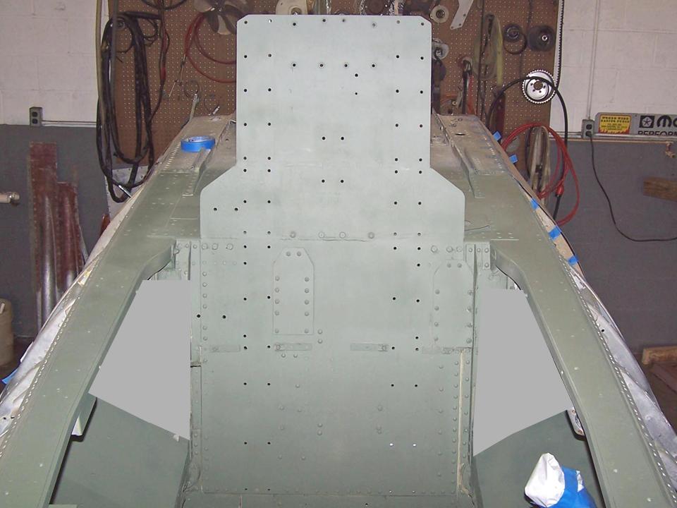 |
Seat rails 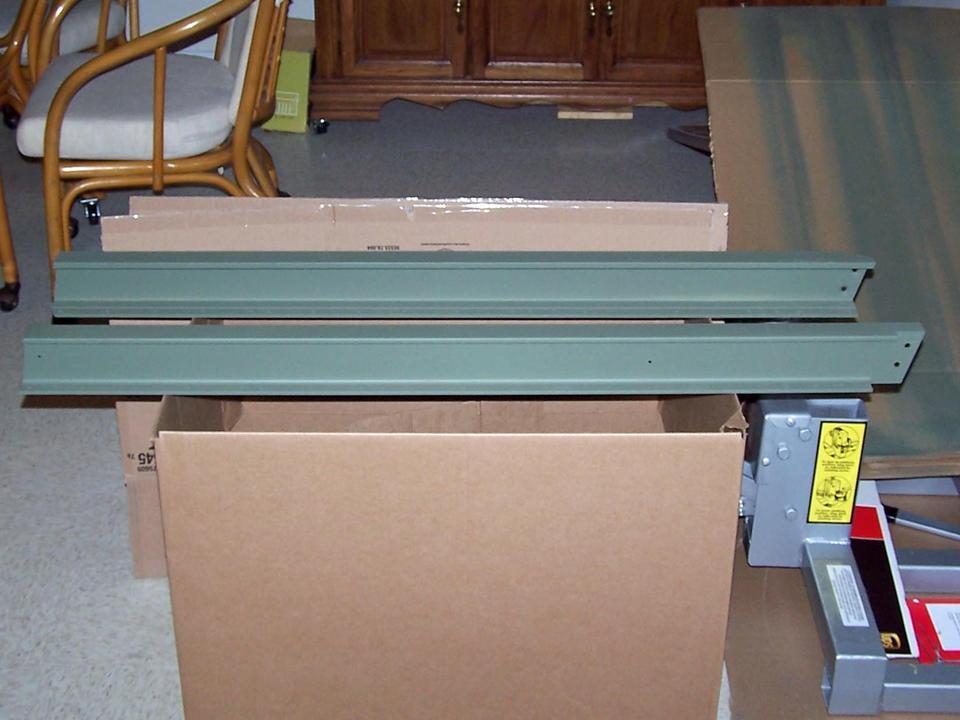 |
Making parts 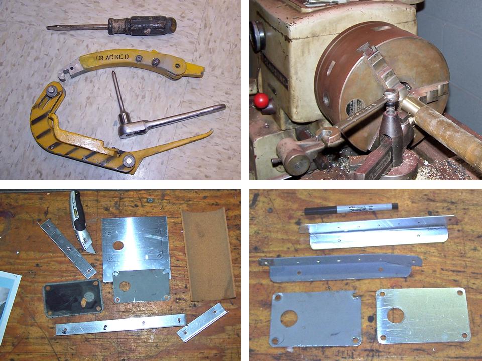 |
The simulator included a "for training only" ejection seat you see -- front and back -- in Figure 3, cell 01. Not quite the real deal, but close enough. (The back of the seat pan shows some damage caused by a cutting torch.) The two pictures in Cell 02 show the cleaned, repaired, and partially primed seat pan on the left and the fully primed seat pan on the right. The next layer of paint will be a zinc-rich gray primer and the final coat will be a color-matched acrylic gray.
In the meantime, I really wanted to see some nicely-finished components. The result is the eye candy you see in Figure 3, cell 03. The leather work involved in the manufacture of new red leather arms rests and a new red leather head rest was well beyond our pay grade, so Steve introduced me to John VanDerWorp, the owner of a custom car interior shop known as
Sew Unique. (I have included the business card for this business and you can read its details if you click on the picture and then maximize it.) As you can tell by looking at the picture, John did a first-class job.|
Training seat pan 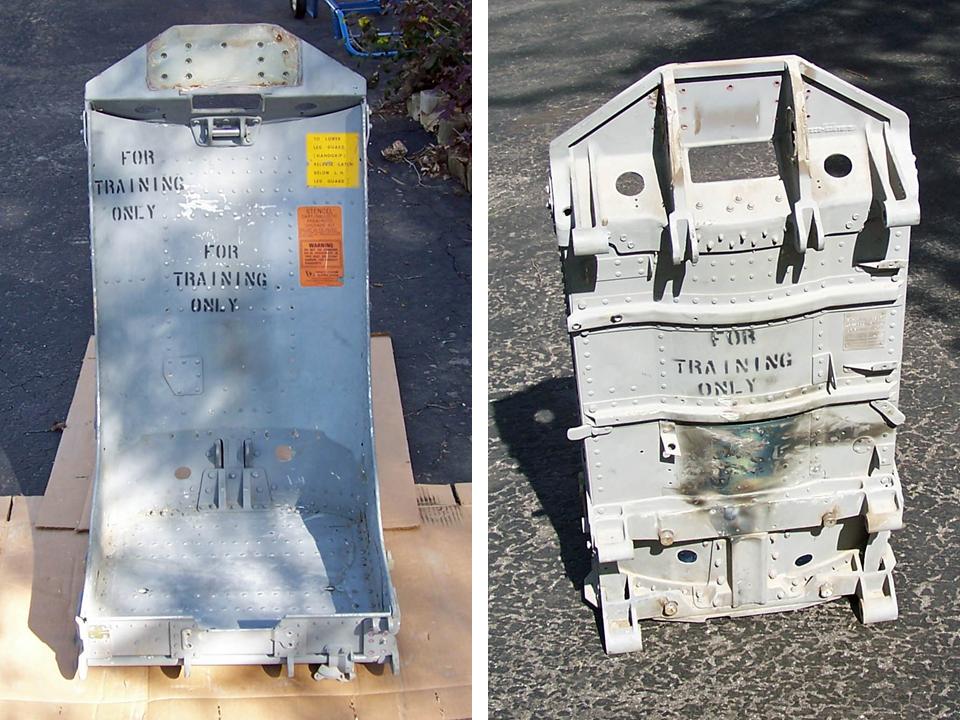 |
Repaired and primed 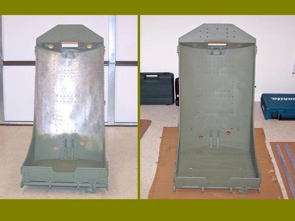 |
Red leather 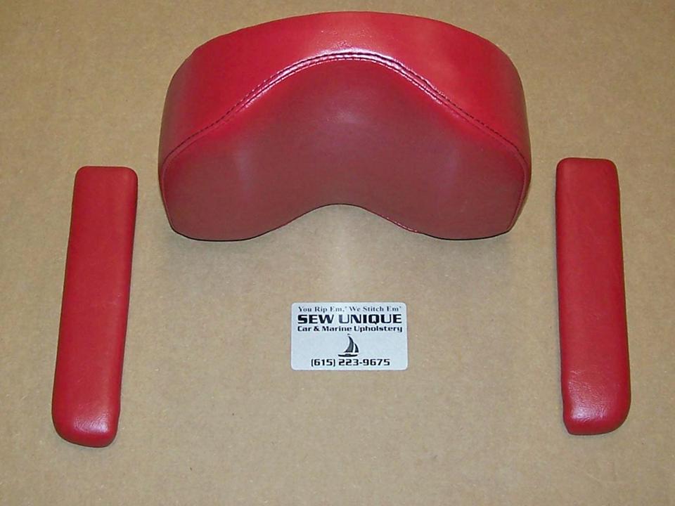 |
Working on the cockpit is never dull, because there are many different components to work on. Figure 4, cell 01 shows that there are ejection seat parts to be made. Steve's machine skills are always available and they are, as you can see, well-honed.
Figure 4, cell 02 illustrates why I spent so much time on the instrument panel. Fortunately, the top of a beet can is just the right size to serve as a template marker. (The text in this composite picture describes the action.) Cell 03 shows the result of many months of work ... the next step will be to install the intrument panel in the cockpit tub.
|
Making parts 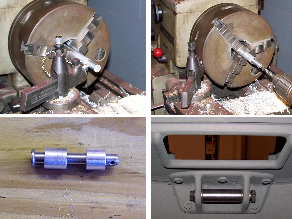 |
Instrument panel work 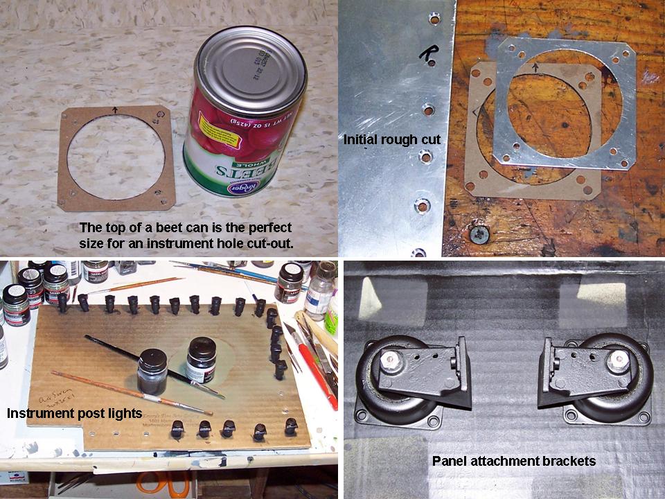 |
Completed instrument panel 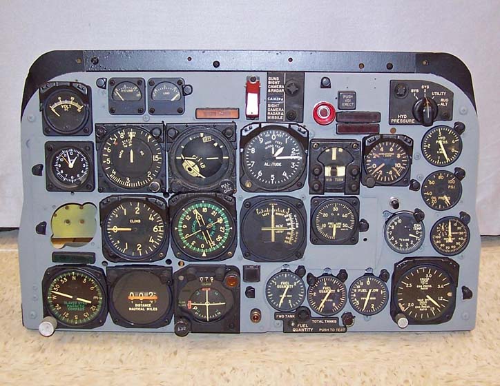 |
As this major "modeling" project moves forward, I will post pictures of the progress we're making. I may not be able to have a real F-100 ... but a properly contructed full-scale model will not be distinguishable from the real thing. Stay tuned.
While the rebuilding and restoring efforts are important, please remember that the main focus of the F-100 project is its database. If you can supply stories and pictures that reflect your experience with the Hun, please do so. (You can click on the Contact me link to send me an email.) The objective is to develop a very comprehensive personal history of the Hun and of the people who flew and maintained her. You and the Hun deserve to be remembered in your own words.
If you want to return to the home page, you can either click on the
Home link shown here or by clicking on the Home link shown on left side of your screen. (You can also use any of the navigation bar links shown on the bottom of the screen to move around this website.)