|
Basic work 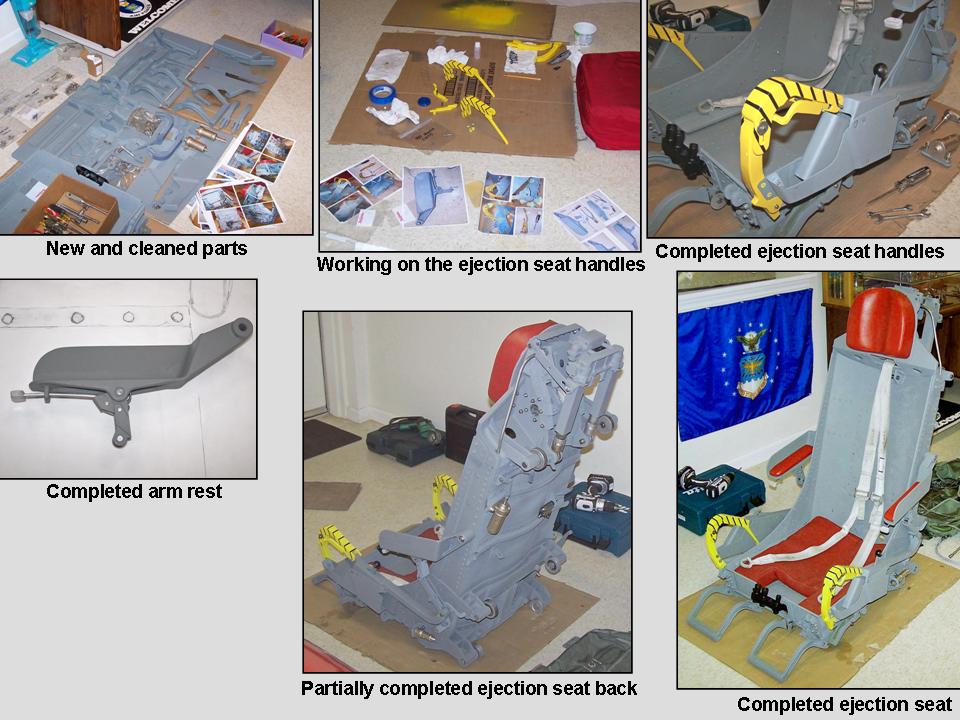 |
Installation 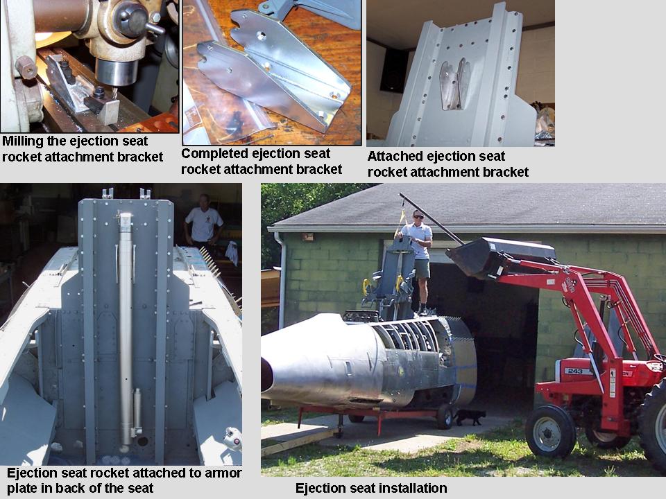 |
Installed ejection seat 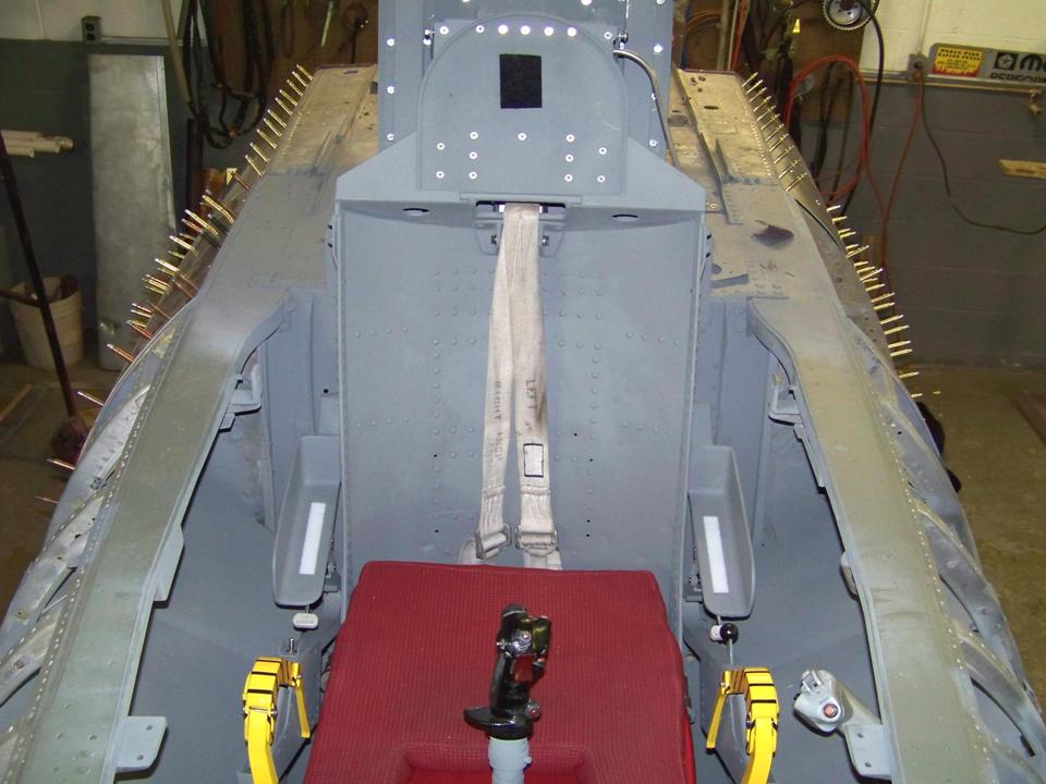 |
After completing the main instrument panel -- see the Cockpit, Part 1 documentation -- it was time to turn my attention to the many remaining cockpit contents. The largest and easily most complex component is the ejection seat. (Naturally, Steve and I kept working on the fuselage in Steve's work shop ... that's where the complex tools are located.) However I can work most of the smaller parts and pieces at home.
Fortunately, the training version of the ejection seat in the simulator provided most of the basic components. (The cockpit, Part 1 documentation showed some of the ejction seat work.) Figure 1, cell 01, shows a collage of pictures that trace the completion process. Cell 02 shows the insertion of the completed ejection seat into the cockpit.
The ejection seat you see in this set of pictures is a lot lighter than the real seat would have been. For example, I continue to operate on the principle that "if you can't see it, it doesn't need to be there." In addition, many of the parts I used are much lighter than the originals. (For example, a motor assembly made of a set of telescoping cans is a LOT lighter than the original!) It would have been possible to lift the seat by hand -- that's how I got it into my van -- but it's a lot easier to use a tractor's front-end loader to lift the ejection seat into the cockpit. Fortunately, Steve has access to such equipment and, more important, knows how to use it. As you can tell by looking at the picture in cell 02, Steve had rigged a piece of angle iron to the front-end loader to facilitate the lifting of the ejection seat. All I needed to do was guide the hanging seat into the cockpit rails and then let gravity do most of the work. (My home-made rollers needed just a bit of fine-tuning, but the insertion of a few washers lined them up perfectly to roll the seat in place.
Figure 1, cell 03 shows the installed ejection seat. Note that I have removed the red leather head rest and both arm rests ... to avoid damage to them while the construction of the cockpit interior continues. The head- and arm rests are attached with Velcro strips, so putting them back on takes mere seconds.
Note: You can enlarge the pictures by clicking on them. After you see the enlarged picture, click on it again to enlarge it some more ... then maximize the window to get an even closer look.
|
Basic work |
Installation |
Installed ejection seat |
The next part of the project was to work on the landing gear panel. Figure 2, cell 01, shows the initial paper trace, the cardboard template, and the new gear panel back plate. Cell 02 shows the primed back plate and cell 03 shows the completed gear panel, ready for installation. I was lucky to have the fiberglass front piece and there are a lot of good graphics companies that can produce or restore any lettering you might need!
Note: You can enlarge the pictures by clicking on them. After you see the enlarged picture, click on it again to enlarge it some more ... then maximize the window to get an even closer look.
|
Basic work 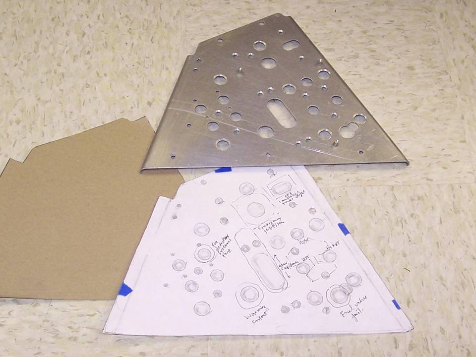 |
Primed panel 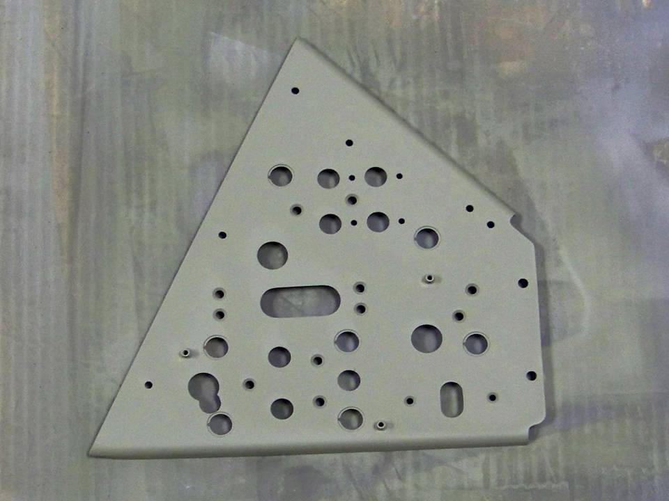 |
Completed gear panel 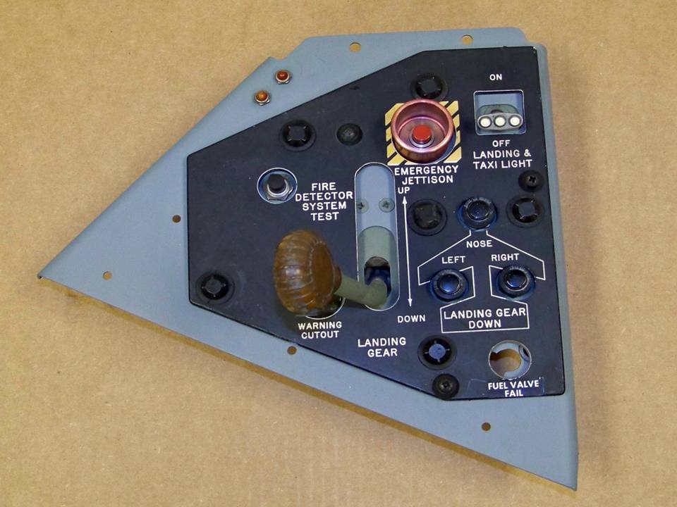 |
Several users of this website have asked me about some of the construction techniques we use to make parts and pieces. For example, there were several questions about the procedures we used to make multi-level "cuts" for the instrument panel. Also, some of you wanted to know how you can make the rounded "bent-in" edges you see on the gear panel. (I suspect that very few of you plan to build an F-100, but the techniques that created many of the F-100 parts and pieces you see on this website can be applied to any project that uses metal.) In any case, the composite picture in Figure 3, cell 01 supplies the answers to these construction questions.
Much of the windscreen was derived from the cockpit procedures simulator. However, the techniques illustrated in cell 01 came in handy when the missing and damaged windscreen pieces had to be made. Figure 3, cell 02 shows the -- finally! -- completed set of windscreen parts and pieces. (You are looking at approximately 200 hours of work spread over more than four months.) The pieces you see in cell 02 were used to make the sub-assemblies you see in cell 03.
Note: You can enlarge the pictures by clicking on them. After you see the enlarged picture, click on it again to enlarge it some more ... then maximize the window to get an even closer look.
|
Construction techniques  |
Windscreen Pieces 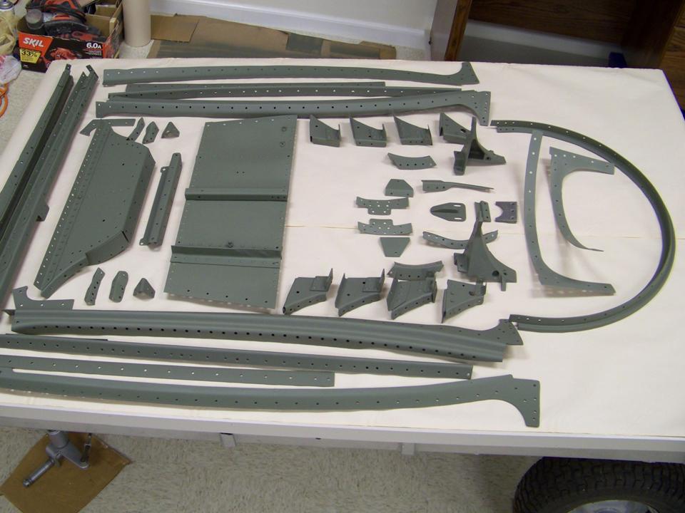 |
Pieces coming together 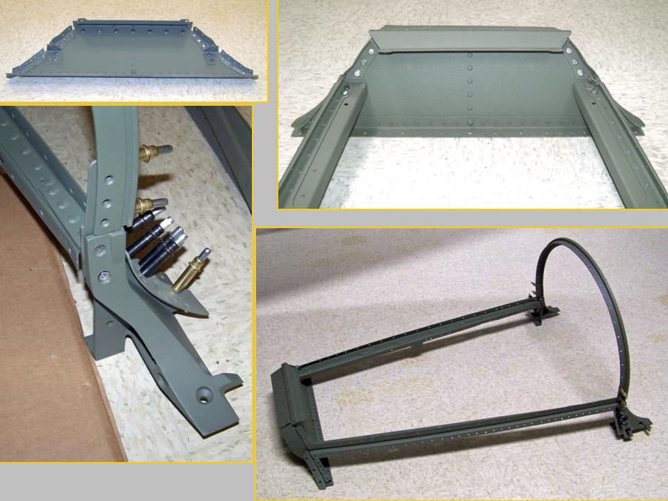 |
Naturally, the techniques you see illustrated in Figure 3, cell 01, are only a few of the tricks of the metal construction trade. If you have taken a look at some of the other restoration menu selections, you saw examples of the parts and pieces created with the help of tin snips, bending tools, shaping tools, files, hammers, and so on. (My wife makes fine jewelry and she knows how to use special hammers and wooden forms to make synclastic and anticlastic metal surfaces that can produce superb jewelry pieces ... the same tools and techniques can be used to make some F-100 parts!) Really complex pieces usually require the use of expensive tools such as milling machines -- and extruded parts require even more specialized tools. Fortunately, there are specialty machine shops that will make such complex pieces ... all it takes is money!
The composite picture in Figure 4, cell 01, shows the collection of carefully-crafted windscreen frame pieces. Cell 02 shows how the pieces fit together to produce the windscreen frame. At this point, the frame pieces are held together with clecos. Cell 03 documents the completion of the installed windscreen -- note that the fillet strips have been added to round out the assembly. At this point, I'm trying to figure out how to make the glass for the center and side windscreen components. Shaping glass to fit the curvatures will probably be much too expensive, so I'll probably use Lexan. In any case, I suspect that it will take a while before I'll be ready to tackle that part of the assembly process ... I'm anxious to get back to working on the fuselage components!
Note: You can enlarge the pictures by clicking on them. After you see the enlarged picture, click on it again to enlarge it some more ... then maximize the window to get an even closer look.
|
Windscreen components 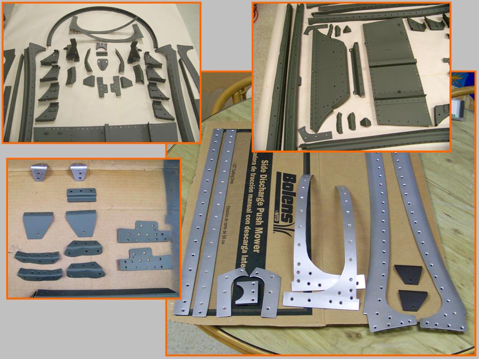 |
Assembled windscreen 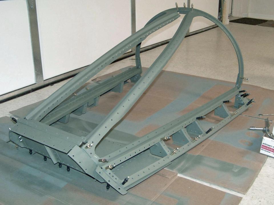 |
Installed windscreen 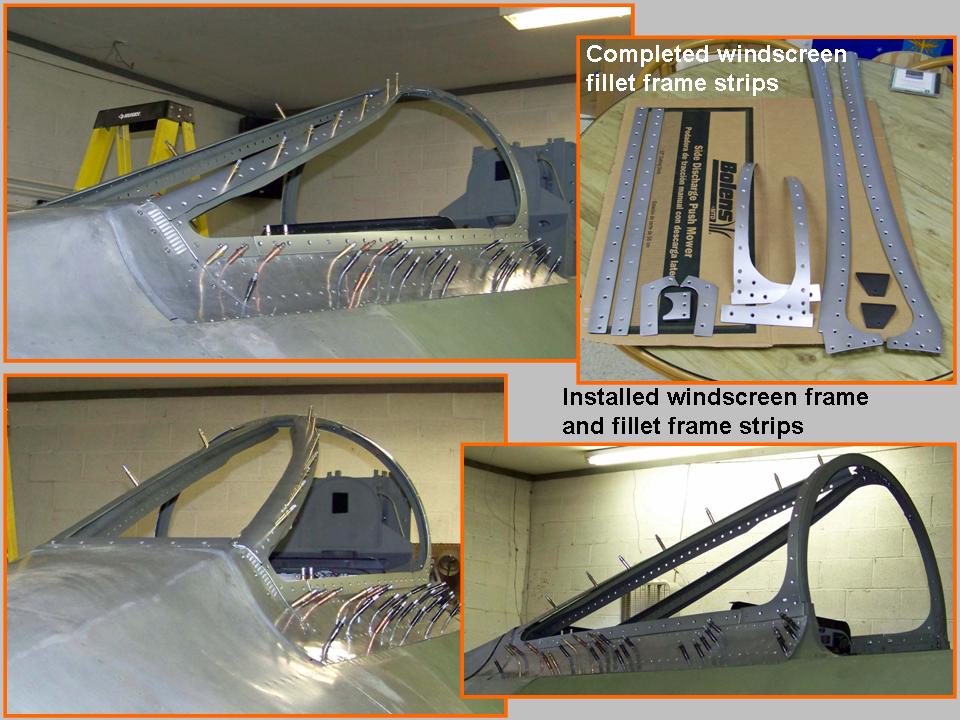 |
After the windscreen work had been finished, I really wanted to get the fuselage segment completed. Therefore, the work on the cockpit components slowed down while the fuselage work accelerated. By December, 2010, the fuselage was completed and the incredibly time-comsuming preparation for the paint job started. I had been told that a successful paint job required intensive surface preparation. No kidding! (Check the Fuselage Parts 9-12 pages to see how the paint job was done ... and to see the fuselage moved to my F-100 museum.)
The well-below normal temperatures during much of the month of December, 2010, hampered the sanding work that was so crucial to a successful fuselage paint job. Unfortunately, sanding generates an incredible amount of dust, thus requiring that it be done outside. Sanding in 30+ degree temperatures, with a strong wind to increase the misery index appreciably, is not what we like to do ... Besides, Bondo doesn't set up well when the temperature gets below 60 degrees Fahrenheit, so that turned out to be another good reason to postpone the outdoor work. In short, I had to start doing all those "small" jobs that were just waiting to get done. In short, it was time to focus on the cockpit work again.
Three tasks were at the top of the to-do list while we waited to resume the sanding. First, I wanted to complete the cockpit pressurization unit. Second, I had to get the instrument panel shroud done, plus the instrument boxes that rested on top of it. Third, the gun sight assembly had to modeled and manufactured.
The cockpit pressurization regulator turned out to be a project all by itself. Although the December weather had forced us inside, I had already spent a lot of time working on it at home in the F-100 "museum." When I finally checked my time sheets after its installation had been done, I discovered that its completion required the investment of about 170 hours, spread over a 6-month period.
Part of my F-100 education has been the realization that you can (almost) duplicate many of the Hun canopy and cockpit components with "off the shelf" materials. For example, the small center component you see in the parts layout in the upper left-hand panel in Figure 5, cell 01, can be very well-approximated with a lawnmower muffler. The main component can (relatively) easily be made from the front section of a discarded electrical pond pump. A toggle switch can be made by using an "upside-down" long-shank pop rivet through an appropriately-sized washer, and so on.
When the whole cockpit pressurization regulator assembly was completed, it had to be installed in the back of the canopy. That turned out to be a lot more "interesting" than it needed to be. Fortunately, Steve was able to hold the piece in place after I had raised the canopy ... and that crucial help let me fasten the first nut in the back of the assembly. One of the first three tasks was now completed. (As you can see in the lower panel in Figure 5, cell 01, some of the ever-present and all-pervasive sanding dust has covered the nice, clean black paint -- but that will be wiped off easily later.)
Note by Pete Felts: Pilots often complained about the pressure regulator's apparent malfunctions, so it was often on the "write-up" list. Actually, that unit worked quite well ... but pilots often put coats, cases, and personal items in back of the canopy, thus blocking it off and hindering its function. Simple advice: don't put stuff in the back of the canopy "shelf."
The composite picture in Figure 5, cell 02, shows the work done to make the instrument panel shroud. Cell 03 documents the work done on the instrument boxes that are attached to the instrument panel shroud. Note that the F-100D tech manual illustration provided the blueprint for the instrument boxes. (I modeled the drop tank fuel gauges in Microsoft Powerpoint, then saved the slides as .jpg files that would be printed to become the instrument faces.) Figure 5, cell 04, documents the same process that was used to make the gun sight. Cell 05 shows the completion of the instrument boxes that are located on top of the shroud. The completed gunsight will be shown in cell 06.
Note: You can enlarge the pictures by clicking on them. Many of the pictures can be enlarged some more by placing the cursor on them and clicking again. Then maximize the window to get an even closer look.
|
Pressure regulator 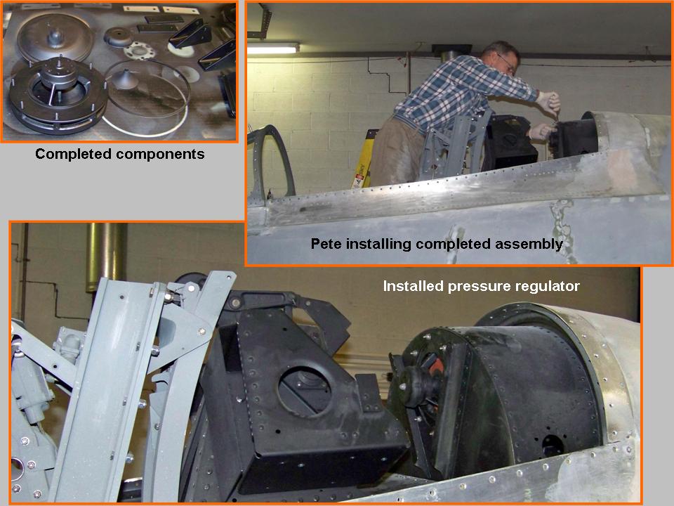 |
Shroud 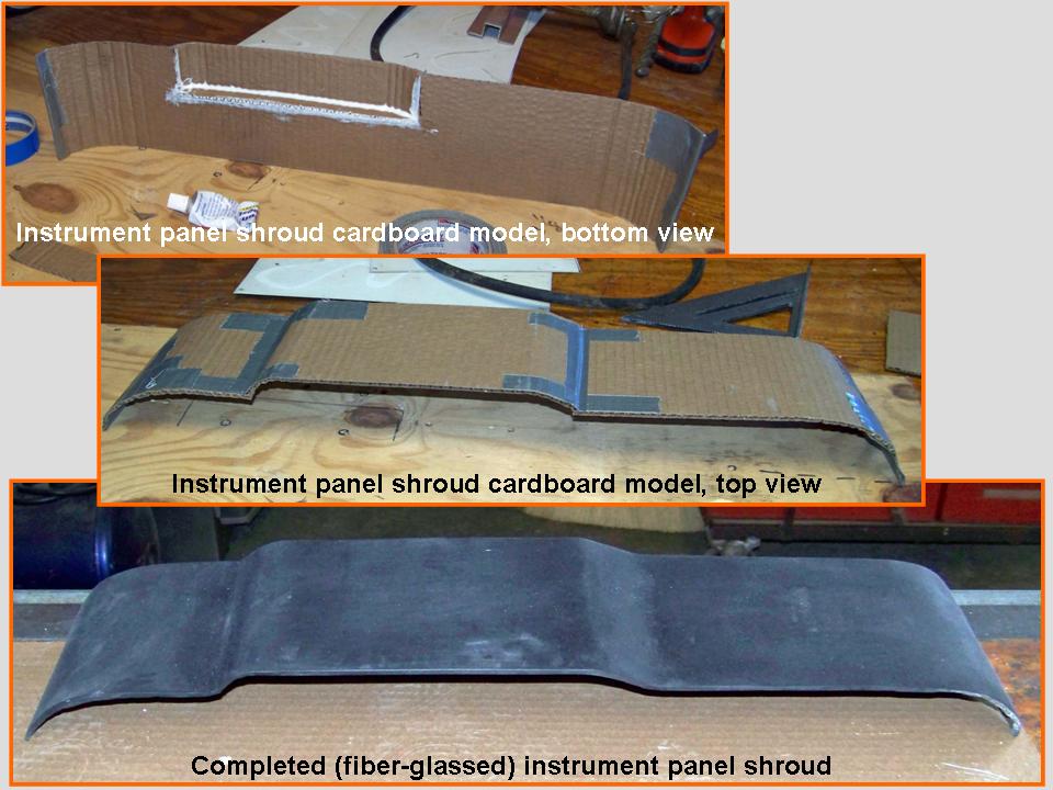 |
Shroud instrument boxes 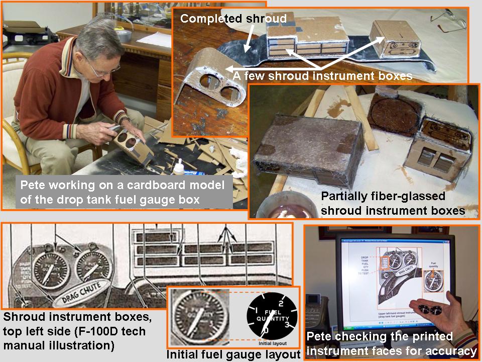 |
|
Gun sight assembly 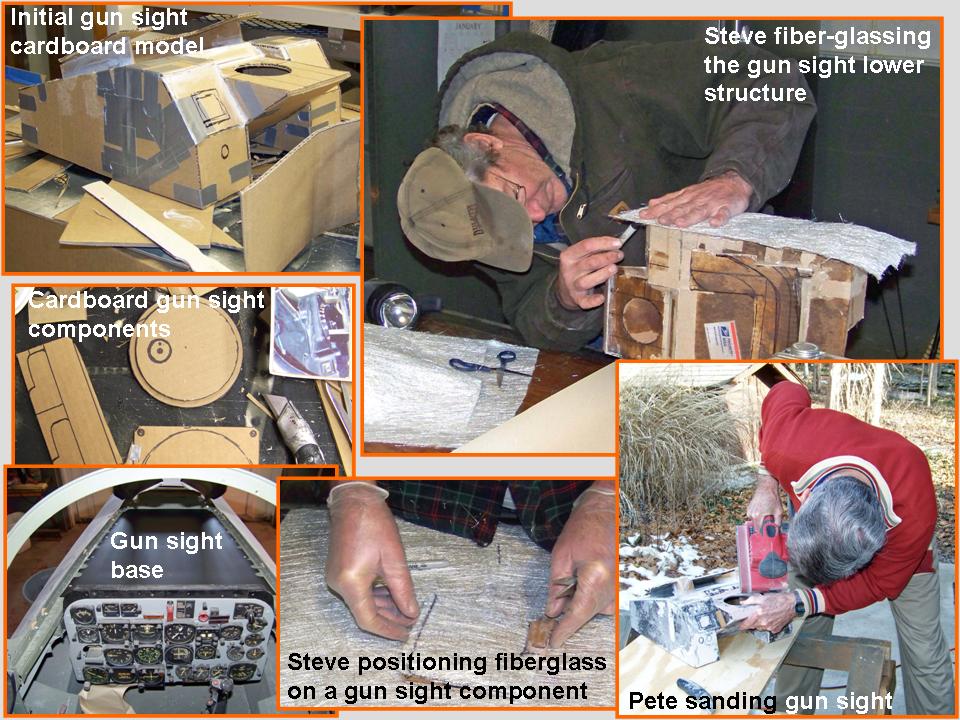 |
Shroud instruments 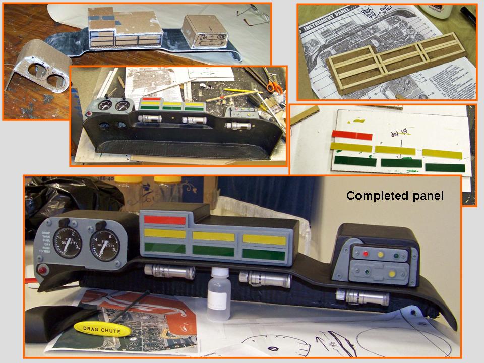 |
Completed gunsight  |
Work progresses on the remaining instrument panels. You'll see that work documented in Cockpit (Part 3) and Cockpit (Part 4). Making instrument panels is very slow work, so it will take some time before I do a lot of cockpit updates!
As this major "modeling" project moves forward, I will post pictures of the progress we're making. I may not be able to have a real F-100 ... but a properly contructed full-scale model will not be distinguishable from the real thing. Stay tuned.
While the rebuilding and restoring efforts are important, please remember that the main focus of the F-100 project is its database. If you can supply stories and pictures that reflect your experience with the Hun, please do so. (You can click on the Contact me link to send me an email.) The objective is to develop a very comprehensive personal history of the Hun and of the people who flew and maintained her. You and the Hun deserve to be remembered in your own words.
If you want to return to the home page, you can either click on the
Home link shown here or by clicking on the Home link shown on left side of your screen. (You can also use any of the navigation bar links shown on the bottom of the screen to move around this website.)