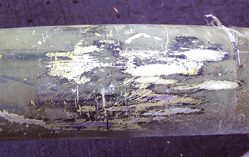
The refueling probe was a welcome addition to the collection. Upon its arrival, the probe appeared relatively undamaged, showing just a few dings. Figure 1 shows a small probe segment that is fairly representative of the probe's condition ... the old camouflage paint is a bit scratched.
Note: You can enlarge the pictures by clicking on them.
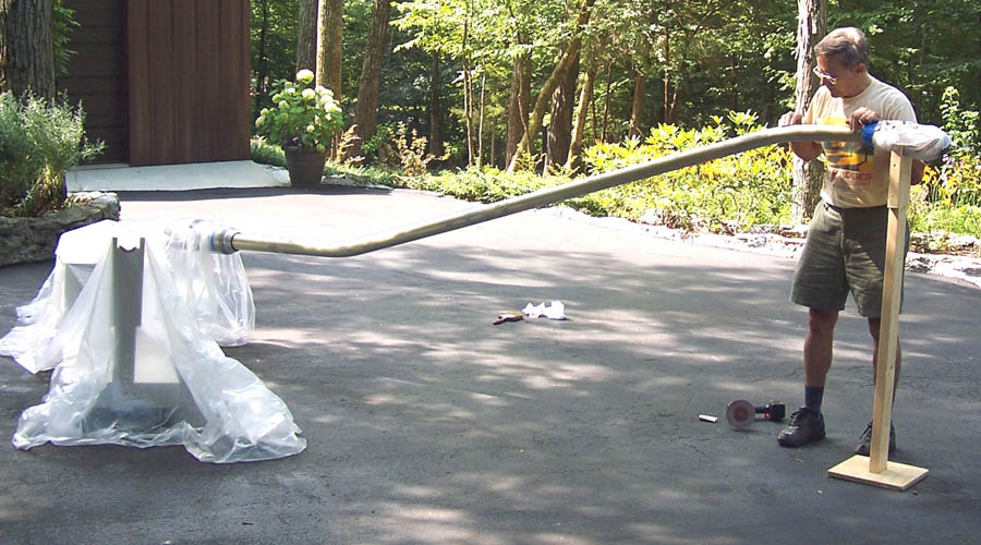
If I have learned anything at all, it is that first appearances may be misleading and that there may be some interesting surprises. After stripping the multiple layers of paint, I discovered that the refueling probe's "tube" sported a thin layer of golden-colored anodization. I also discovered that there were some small metal fatique fractures and that many small dents were very visible once the tube was clean. Never mind ... lots of filling and sanding took care of hiding the damage. Figure 2 shows sanding in progress ... at this point, my work log showed a time investment of just over 26 hours and the sanding is only in its first stages. (The time does not include building the stand on which the probe rests.)
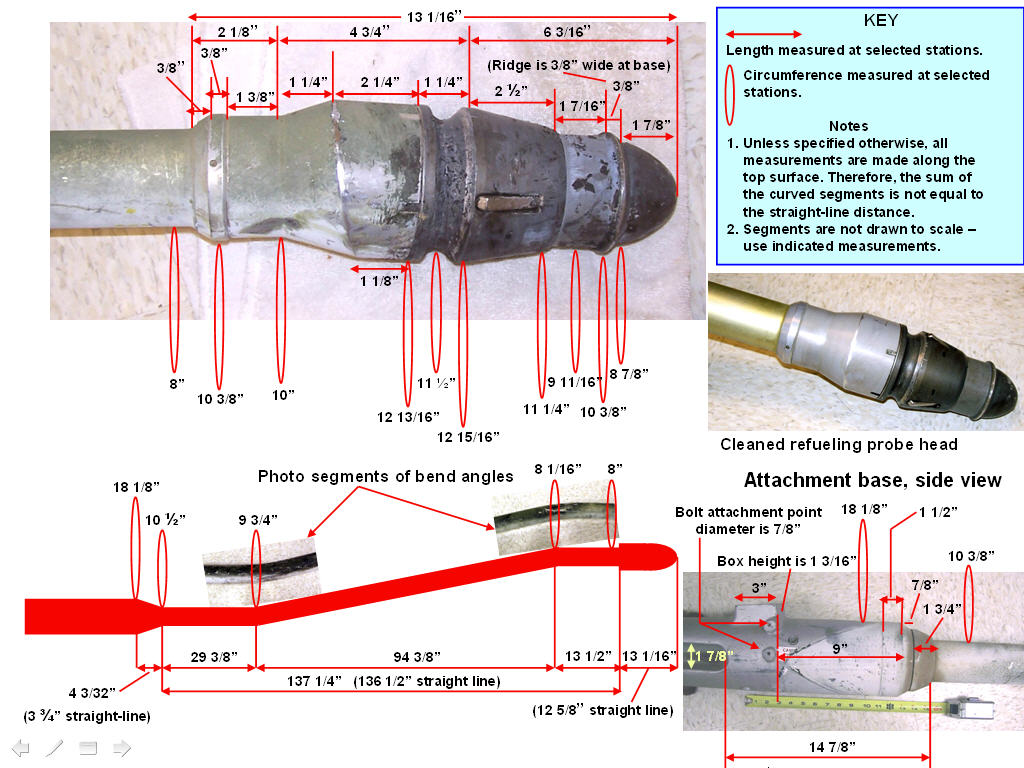
I hope that Figure 3 will be a good aircraft modeling template for serious modelers. All the measurements shown here are the result of many hours of measuring and remeasuring ... I have tried to ensure that the measurements are accurate to the nearest 1/32 inch.
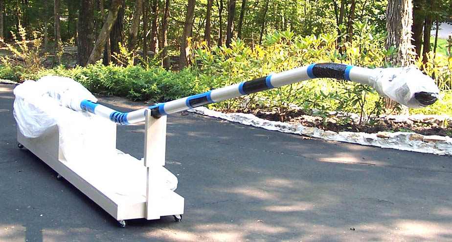
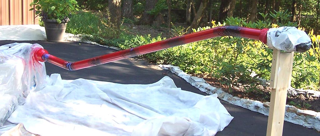
I planned to use the red/white bands Thunderbird paint scheme on the refueling probe. The secret to a good paint job is preparation ... that's why the filling and sanding were so important. After the probe looked smooth enough for a paint job, I sprayed the self-etching undercoating on ... and then did a final sanding with very fine sandpaper. Next, two coats of white laquer were applied. After the white coat was properly cured, I taped the probe for the application of the red lacquer. Measuring the tape points was done multiple times ... until the final band at the front end matched the official measurements exactly. Figure 4 shows the taped probe. (I used black plastic to protect the white lacquer and blue painter's tape to seal the edges.)
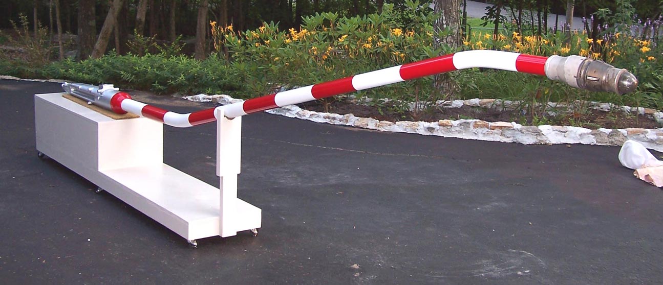
After the taping was completed, I was ready to spray the final two coats of red lacquer that would become the red bands on the white background. display stand. Figure 5 shows the probe after the red lacquer was applied.
After the red laquer was applied, the tape had to be removed carefully. If you move the tape too quickly, the lacquer edges may pull. If you wait too long, the dried lacquer may "splinter" and the line will not look clean. Figure 6 shows that the job was completed succcessfully. (Another 50+ hours invested.)
While the rebuilding and restoring efforts are important, please remember that the main focus of the F-100 project is its database. If you can supply stories and pictures that reflect your experience with the Hun, please do so. (You can click on the Contact me link to send me an email.) The objective is to develop a very comprehensive personal history of the Hun and of the people who flew and maintained her. You and the Hun deserve to be remembered in your own words.
If you want to return to the home page, you can either click
on the
Home
link shown here or by
clicking on the
Home
link shown on the navigation bar on the left side of your screen.
(You can always use any of the navigation bar links to move around
this website.)