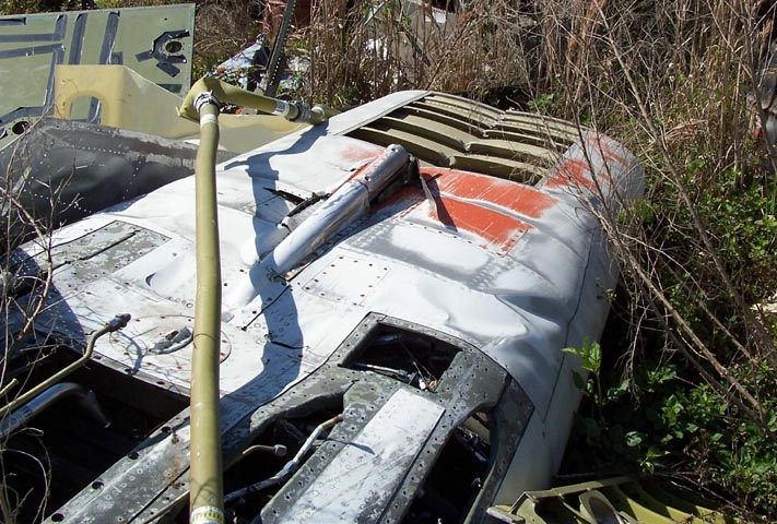
In March of 2005, a long-time Florida friend on mine, Dick Davidson, called to tell me that he spotted some F-100 parts and pieces at Tom Reilly's Flying Tiger Warbird Restoration Museum in Kissimmee, Florida. A week later, my wife (Anne) and I drove to Kissimmee to check out the "heads up" we received. And, yes, we found the front 8' 3" bottom piece of an F-100. (See Figure 1.) Tom Reilly delivered the piece to the F-100 building on 5-July-2006.
Note: You can enlarge the pictures by clicking on them.
The front bottom fuselage section you see in Figure 1 had been subject the hot and humid Florida subtropical weather for a long time. It did not take long to discover that the buckled skin plates had to be replaced and that much of the internal structure would have to be rebuilt. Fortunately, I was introduced to Steve Rettell, a master aircraft and race car builder. Steve was willing to tackle the restoration project and began by taking all the skins off the frame ... only to discover that the frame was mangled in many places and badly corroded in other places. Figure 2 shows a collage of pictures that illustrate the extent of the damage. (Incidentally, cell 3 shows that we have already removed the damaged frame and replaced it with plywood. Cell 5 shows the lead weights we removed. These weights -- over 168 pounds -- were used to provide the proper balance for the aircraft.)
|
Frame Damage 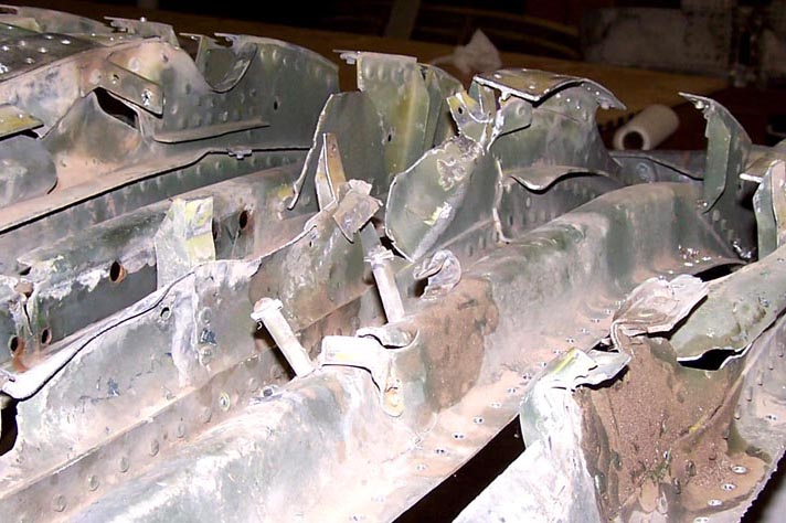 |
Frame Damage 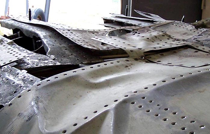 |
Frame Damage 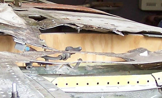 |
|
Panel Sections 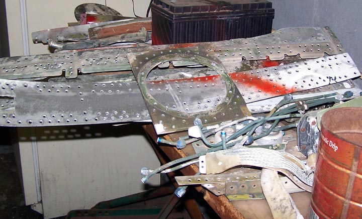 |
Lead Weights 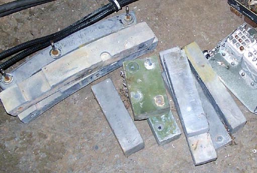 |
Bottom Skin Plates 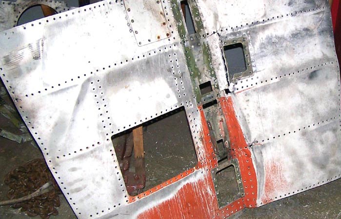 |
Given the extent of the frame and skin damage, Steve recommended that we replace the components, rather than try to repair them. It would be much easier to simply use the original damaged pieces as templates for new pieces. Basically, this approach will produce a replica, rather than a restoration. In short, I will wind up with a 1:1 "model" of the original and I will keep just a few of the old damaged pieces as a reminder of the work that had to be done and, of course, as historical "touch stones." We will also use this front fuselage piece as the basis for the major project -- building the entire fuselage up to the burner can section.
Figure 3 shows the start of the building process. (And years of work are yet to
come ...)
Cell 1 shows Steve at work ... measuring and remeasuring. There is much wisdom in the
builder's first commandment: Measure twice, cut once. Actually, given the cost of
aluminum and the time and effort it takes to cut such panels, measuring five or even
six times before cutting is good policy.
Cell 2 shows me at the cutting machine. Thanks to Steve's patient and expert teaching,
I am learning to mark, cut, drill, deburr, use clecos, rivet, fill, and polish. One
very valuable lesson learned: Trying to mark a flat piece of aluminum to match a
curved piece of Hun skin is a major challenge.
Cell 3 shows a freshly cut inspection panel. The edges still need smoothing and
polishing, but the tough cutting job is done. And, yes, the deburring of the drilled
holes will be next.
Cell 4 Shows me working with the deburring drill. That's one of the first jobs Steve
let me do by myself ... after he made sure that his teaching had taken root, of
course.
Cell 5 Shows that drilling is a major time consumer. The number of rivets in a Hun
skin is amazing ... and each rivet requires careful marking, drilling, and deburring.
The process quickly becomes routine -- mark, drill, insert a cleco, mark the next
one, drill, insert a cleco ... and so on. When that job is done, take the plate off,
debur on both sides, and vacuum all the drilling and deburring debris from the
surrounding area. Next, re-attach the piece with the clecos and when you are satisfied
with the fit, pull the first cleco, debur the hole to match the rivet head, insert the
rivet, let the rivet gun do its magic, and move on to the next cleco. It takes time --
LOTS of time -- to get the job done, but each minute is a worthwhile investment in
getting the fuselage built. Spending time in Steve's shop is always a pleasure,
especially since Steve is there to provide the all-important guidance.
Cell 6 shows Steve looking over some major progress. He's holding the pitot mast
bracket and we have the pitot mast covers ready to install. At this point, the skin
plates require a lot more rivet hole drilling ... and only a few rivets have been
inserted. The duller aluminum sections show the effects of filling ... there will be
many hours of wet-sanding and polishing ahead.
|
Master Builder 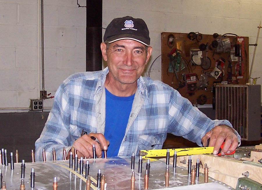 |
Cutting Metal  |
Inspection Plate 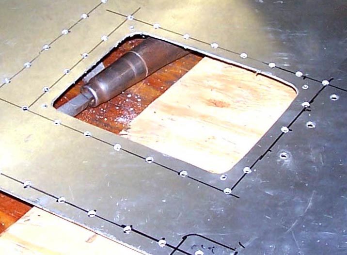 |
|
Deburring 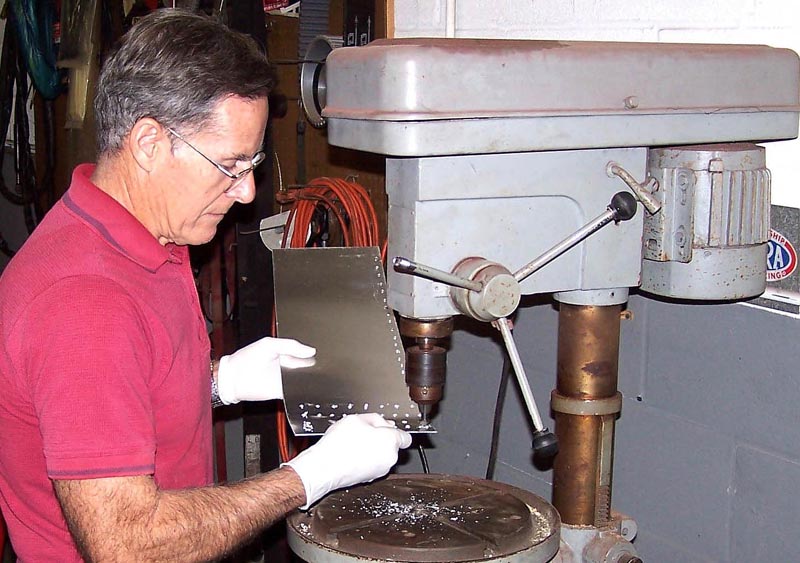 |
More Drilling 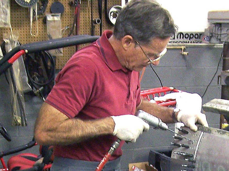 |
Making Progress 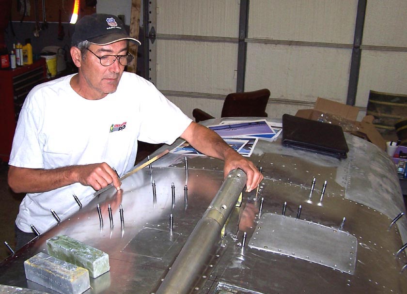 |
Thus far, you have seen the work done on the bottom of the front fuselage section. After Steve flipped that section and placed it in the carpet-lined plywood cradles, the work started on the top section and on the intake's lower inside panels. (When the fuselage section is upside-down, it's a LOT harder to measure the lower intake inside panels -- and trying to cleco and rivet those panels while you're lying on your back is definitely not a good idea. Not to mention the fact that working on the "hood" and the top fuselage panels is a lot easier when the fuselage is right-side up ...)
Figure 4 shows the progress made on the top portion of the front fuselage section. Cutting
the panels to match the frame is easy if you have a paper tracing of the actual part.
Therefore, it's very helpful if you have access to the real airplane components so that
you can trace the panel outline and mark all the fastener holes. (Having very detailed
photos helps, too. That's why I'm really grateful to Albert "Smitty" Smith, who was able
to get me to the beautifully restored F-100D at the Arizona Air Guard base in Tucson.)
Cell 1 shows a top fuselage panel. The panel was cut to match the paper tracing you see
taped to the aluminum. After the panel was cut, it was bent to match the fuselage frame.
Next, the paper was taped back over the panel to serve as an alignment aid so that the
holes for the fasteners could be drilled in exactly the right place.
Cell 2 shows the initial cut of the last inside intake panel. Steve has already drilled
a few holes that match the holes in the intake frame so that the panel can be held in
in place -- with clecos -- while the remaining holes are marked to align with the holes
in the frame.
Cell 3 shows the front fuselage section right-side up ... and almost ready for basic
clean-up work. Almost all of the panels are in place and they are all properly aligned at
this point. (I'm still working on the gun radar cover, but that will be a relatively
minor fiberglass job. But there is much filling and sanding to be done yet ...)
Incidentally, note that the fiberglass gun blast panels are in place -- you can see one
of them in this picture.
|
Top Panel 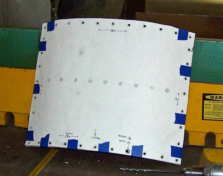 |
Intake Panel 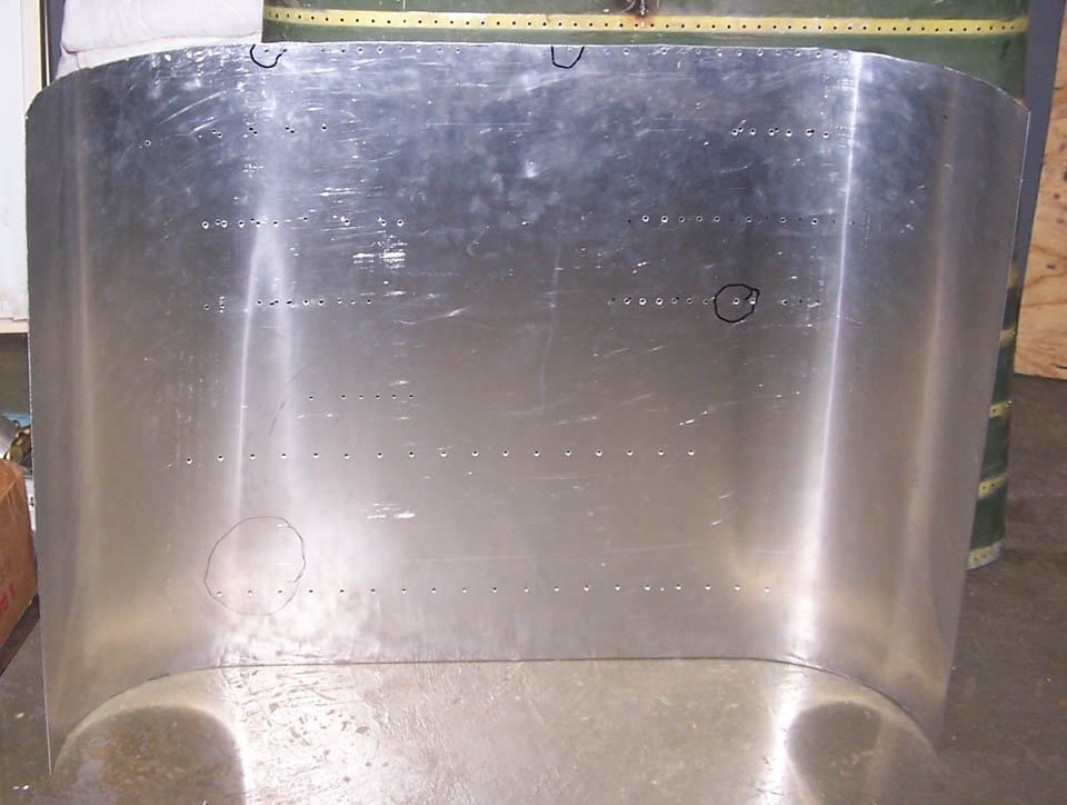 |
Fuselage Front 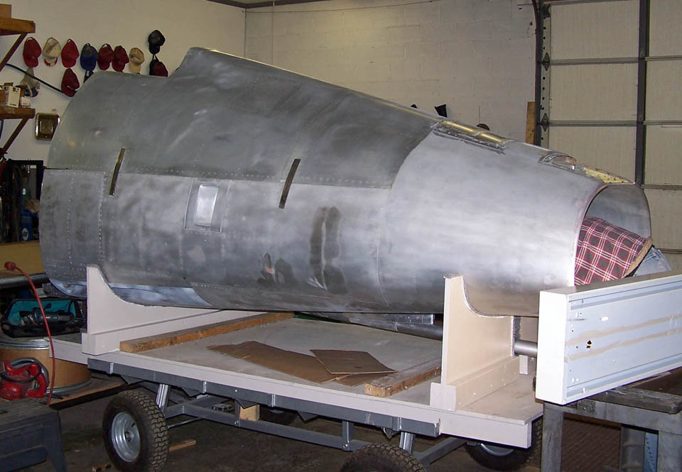 |
As this major "modeling" project moves forward, I will post pictures of the progress we're making. I may not be able to have a real F-100 ... but a properly contructed full-scale model will not be distinguishable from the real thing. Stay tuned.
Special note: Some years ago, I lost an opportunity to buy an F-100 cockpit procedures trainer. Although the cockpit in this trainer is not functional, it looks real enough ... and, most important, it includes the windscreen and the canopy. Having this piece of equipment will save at least a year of construction time. If you can help me find such a trainer, please contact me.
I need a set of F-100D fuselage blueprints to ensure that the formers and skin plates we cut are accurate. If you can give me some "heads-up" about where to buy such blueprints, I would sure like to hear from you!
If you want to return to the home page, you can either click
on the
Home
link shown here or by
clicking on the
Home
link shown on the navigation bar on the left side of your screen.
(You can always use any of the navigation bar links to move around
this website.)