|
Details 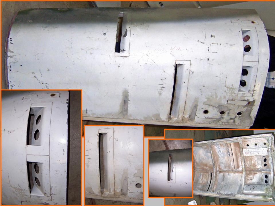 |
Template 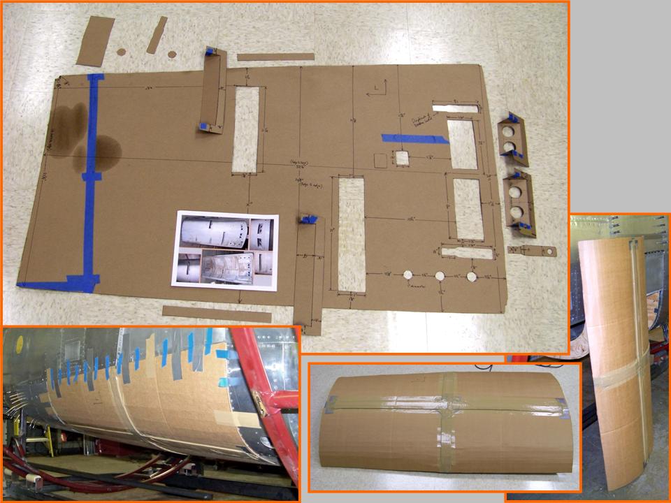 |
Taped in place 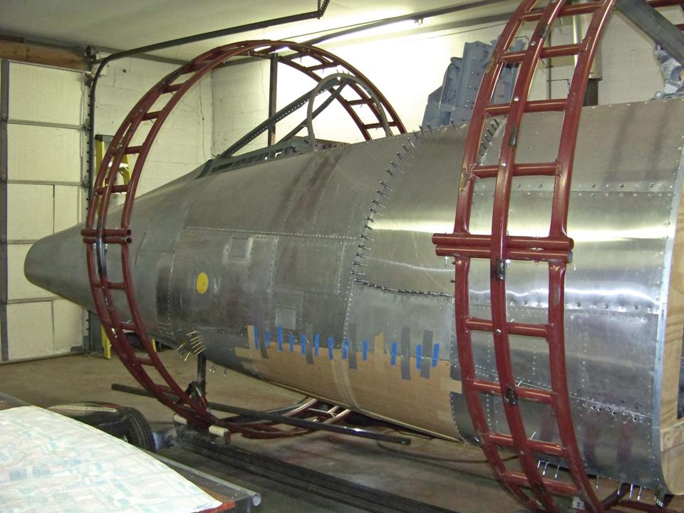 |
One of the more complex fuselage components is the gun bay door. Fortunately, Dean Demmery, the Carolinas Aviation Museum's curator, had given me permission to trace any and all parts of the F-100D he was restoring. (You can check the tracing work Mark Brown and I did by looking at the Fuselage Part 4 page.) We also took over 100 pictures of the fuselage components and details.
Although I still had to complete the ammo door details -- you can check that part of the project on the Fuselage Part 5 page -- I like to work on several components simultaneously. That approach keeps the effort more interesting and it also lets me enjoy some measure of progress as the major components come together. (This is a very lengthy and time-consuming project, so it's encouraging to see at least some periodic evidence that I'm actually getting somewhere!)
Getting started on the gun bay doors -- there's one on each side -- was a fine way to see some major pieces "round out" the fuselage. Figure 1, cell 01, shows a composite picture of the left gun bay door and its components. (The gun bay door belonged to the Carolinas Aviation Museum. Dean Demmery was kind enough to let me take pictures and trace all of the gun bay door details.) The composite picture in Cell 02 shows the cardboard template. It also shows the corrugated cardboard copy I made to check its fit on the fuselage frame. The corrugated cardboard, plus some extra cardboard strips taped in place, was sufficiently rigid to maintain its shape. (Trying to tape a "floppy" piece of cardboard to a curved frame is not a good idea.) Cell 03 shows the cardboard copy's final fit to the fuselage frame. (This is what more than 2.5 years' worth of work looks like.)
Note: You can enlarge the pictures by clicking on them. Many of the pictures can be enlarged some more by placing the cursor on them and clicking again. Then maximize the window to get an even closer look.
|
Details |
Template |
Taped in place |
Note by Pete Felts:
The structures you see in the gun bay door are vent and purge openings. Note
that the openings have an angled baffle at the back of the opening. The
purpose of these baffles is to create suction as the slipstream flows over
the door. The holes at the back of the door purge the link bay.
To make it easier -- a LOT easier! -- to work on the gun bay doors, the fuselage had to be rolled 90 degrees. (Lying on your back on a hard concrete floor is not the best way to work. For one thing, getting a lot of aluminum debris in your face is annoying at best, even given the fact that safety glasses at least keep the stuff out of your eyes ...)
In Fuselage, Part 5, you saw the design and manufacture of the roll cage. It was now time to put that design to the test. Just to make very sure that the roll cage would not flex, Steve had welded additional braces to the roll cage structure ... and that extra caution took a load off our minds as the tractor front loader was used to roll the whole cage -- with the fuselage inside it -- on its rollers.
To roll the cage, we threaded a chain through the lower cage bars and then locked the chain over the tractor's front-end loader. Lifting the front end loader would roll the cage. Naturally, when we ran out of vertical lifting space for the loader, we had to remove the chain, re-thread it through the lower cage bars, and repeat the process. Each repetition gave us a maximum of about 20 degrees of roll. The pictures in Figure 2, cells 01-03, illustrate the process.
Note: You can enlarge the pictures by clicking on them. Many of the pictures can be enlarged some more by placing the cursor on them and clicking again. Then maximize the window to get an even closer look.
|
First roll 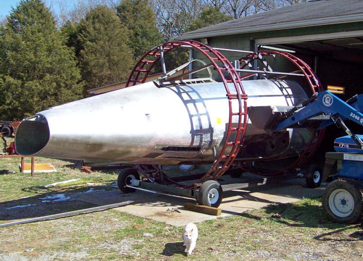 |
Getting there  |
Completed roll 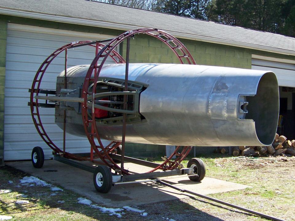 |
After the fuselage roll was completed, we could start work on the gun bay doors. However, I also wanted to start the work on the spline section. Since Steve and I worked on the fuselage in his building two days a week, we could speed up the process by doing some of cleaner portions of the "manufacturing" process in my F-100 Building. (I had done most of the "clean" portions of the work -- such as drafting, paper trace lay-outs, cardboard modeling, and so on -- in the F-100 Building. Messier jobs that did not require special tools -- such as cutting the plywood formers -- were done outside my F-100 Building.)
The pictures in Figure 3, cells 01-03, show the progress on the spine section. Thanks to the tracings supplied by Pete Felts, I could finally complete most of the spine segments. Pete will trace the two sections just aft of the canopy during the next few weeks and then I can begin the challenging job of getting the entire spine portion done. At this point, I'm working on the Ram Air Turbine (RAT) section ... and I'm converting the cardboard into metal. You will see the progress after I do the next update of this page.
Note: You can enlarge the pictures by clicking on them. Many of the pictures can be enlarged some more by placing the cursor on them and clicking again. Then maximize the window to get an even closer look.
|
Traces and models 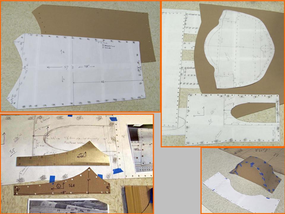 |
Models 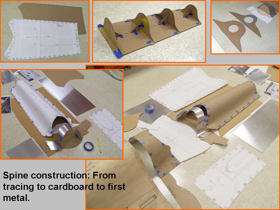 |
Spine panels 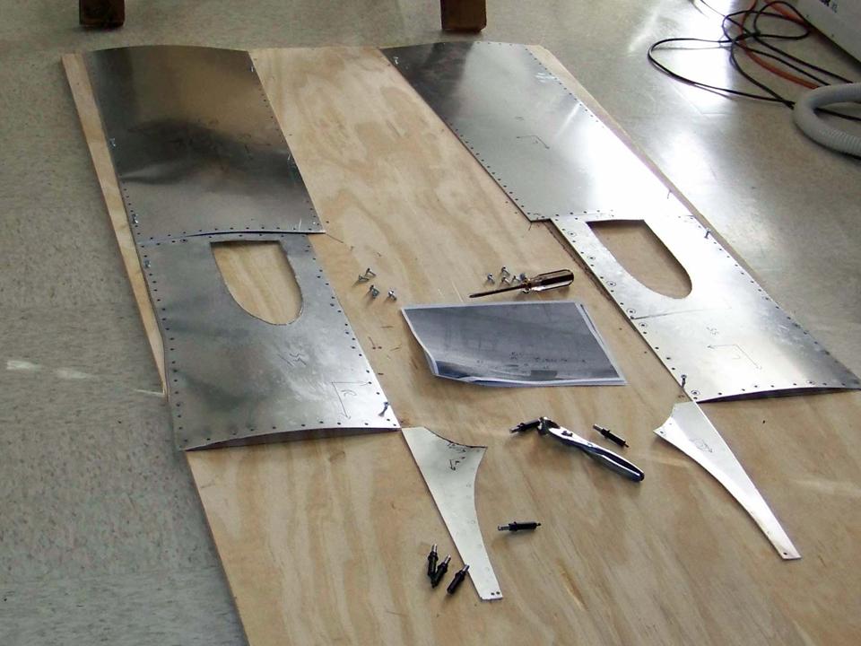 |
You saw in Figure 3 that the paper tracings and cardboard models became the basis for the aluminum panels shown in cell 03. That work was challenging enough ... and now it was time to make the plywood formers that would define the spine shape. The problem was that the spine section curvatures were pure guess work -- initial cardboard cut-outs were, to put it charitable, well off the mark. However, after multiple false starts and even more numerous corrections in the "almost right" heavy cardboard formers, I finally felt sufficiently confident to transform the cardboard into plywood.
Figure 4, cell 01, shows the initial plywood formers. A heavy-duty belt sander was a critical tool at this point -- each time a panel was taped to a former, poor fit became evident. The belt sander would be used to correct each former's shape, after which the panel would be taped to the former again ... and the need for additional corrections became evident. (Patience is a really valuable virtue ...)
Figure 4, Cell 02 shows additional spine panels and some of the many metal stringers that would be used to form anchors on the plywood forms. These stringers would also be the way to attach the skin panels to the (plywood and metal stringer) frame. The lower right-hand panel in the composite picture shows that progress has been made! Cell 03 shows a completed spine section ... finally, a very good fit.
Note: You can enlarge the pictures by clicking on them. Many of the pictures can be enlarged some more by placing the cursor on them and clicking again. Then maximize the window to get an even closer look.
|
Formers 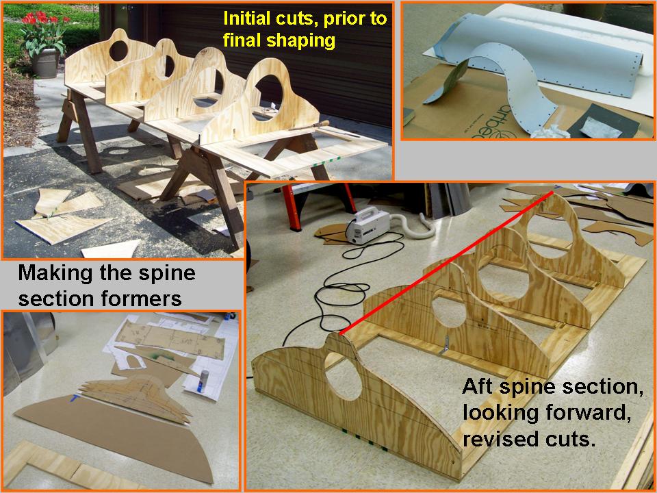 |
Initial layouts  |
Initial construction 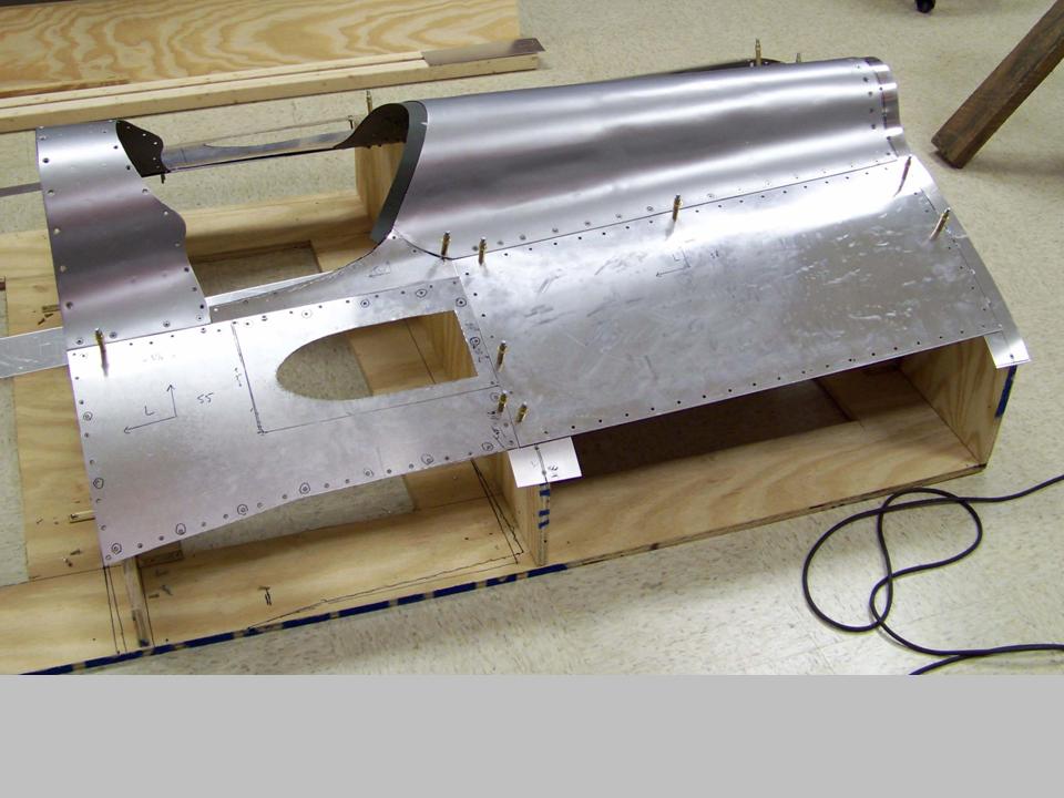 |
Figure 4, cell 03 shows that much progress has been made ... and that much remains to be done. The next job will be the shaping and placing of the Ram Air Turbine (RAT) panel. (The cardboard model seems to fit, but there is a lot of metal bending and shaping yet to come.) After that, I'll work on the saddle. Pete Felts was kind enough to provide a really good tracing, so I'll have to start cutting metal soon. Since I'm an optimist, I hope to have the spine section done by July, 2009 ... (I'm writing this statement on 24 April, 2009.)
Given the fairly complex multi-directional bends in the RAT (Ram Air Turbine) panel and the center section of the saddle, I spent some time trying to devise ways to get those bends "just right." During the search for the right bending tools and techniques, I did a lot of experimenting ... and discovered that trees of varying trunk thicknesses make VERY effective bending tools. Therefore, shaping the RAT and center saddle sections turned out to be less of a problem than I had feared. (Cedar trees have nice, smooth trunks, so they turned out to be really good "tools.") I also discovered that the sharper bends at the edges could be handled by pounding them with a rubber hammer across a 4-inch section of heavy PVC pipe.
Figure 5, cells 01-03 shows the RAT and saddle "manufacturing" process and the initial fit of the RAT and (center) saddle panel sections in the spine segment. Cell 04 shows the cutting of the saddle side panel latch holes. Cells 05-06 show the crush panel section work from start to (near) completion. At this point, I cannot (yet!) do the rivet work that will fasten the crush panel sections to the frame, so the clecos will stay in place for a while longer. The riveting task will be completed when I have built the back section of the canopy to make sure that the canopy will open properly. (The composite picture you see in cell 06 was made on 18 July, 2009 ... so the spine section work is right on target.)
Note: You can enlarge the pictures by clicking on them. Many of the pictures can be enlarged some more by placing the cursor on them and clicking again. Then maximize the window to get an even closer look.
|
RAT work 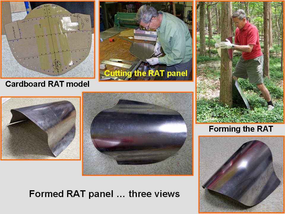 |
Saddle work 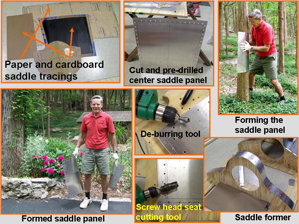 |
Fitting the panels 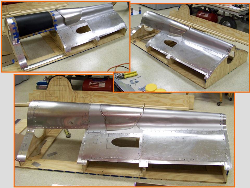 |
|
Saddle side panel 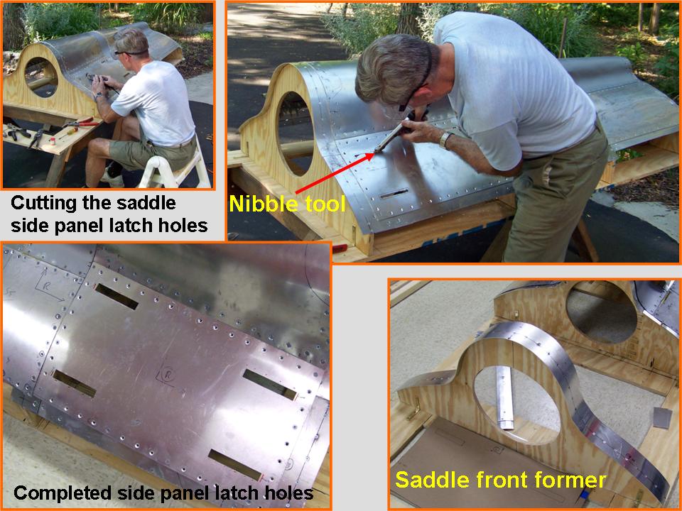 |
Initial crush panel work 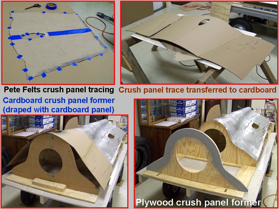 |
Crush panel completion 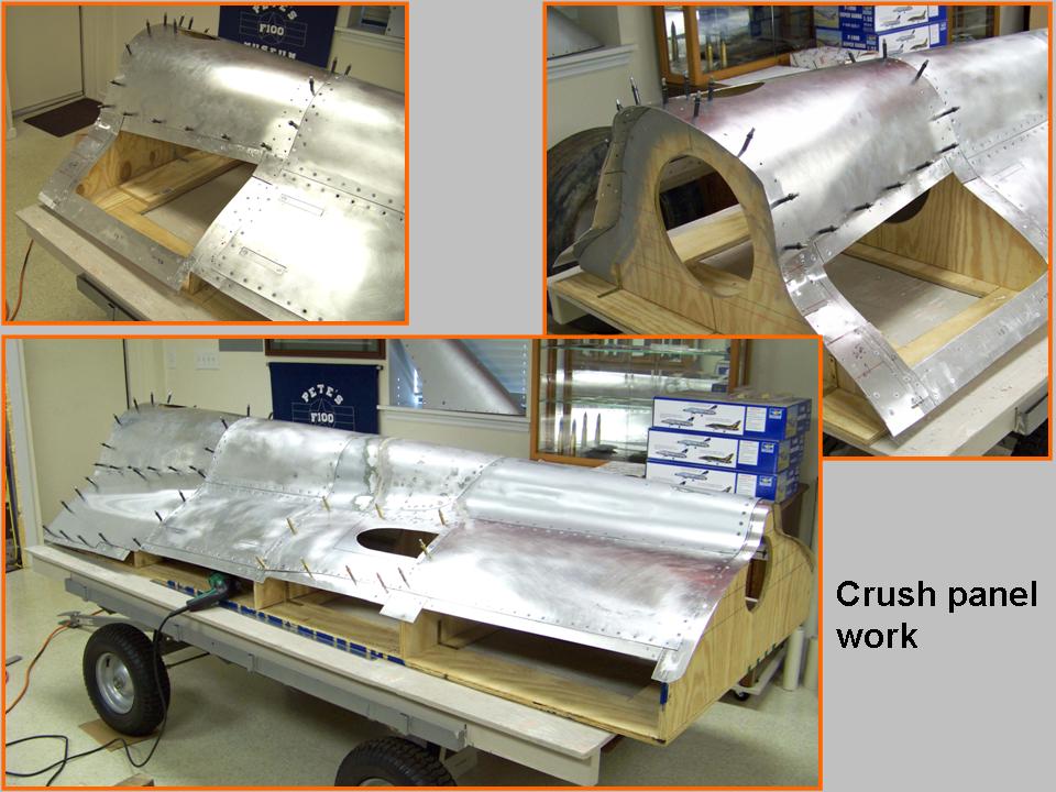 |
Figure 5, cell 6, Heat Exchanger Duct (HED) panel openings, but much work remained to be done to make and install the duct tube. Fortunately, Steve had found a piece of aluminum pipe that had an "exactly-right" diameter and wall thickness. Steve proceeded to cut the pipe section diagonally to match the correct installation angle and then hammered the aluminum pipe into shape to flare the pipe end into the back of the HED panel. He then welded the exhaust pipe to the panel and then used Bondo to seal the edges.
Although I had cut, shaped, and drilled the HED panel, much work remained to be done. First, the photos and the paper rubbings that I had made showed that the HED panels are fastened to the fuselage frame with 9/16" flush-head Dzus fasteners. Therefore, I had to widen the drilled holes and counter-sink them to match the Dzus heads, thus ensuring that the Dzus heads were flush with the panel skin.
I had used the 9/16" Dzus fasteners before -- but I discovered that I had only eight left, far too few to finish the HED panels. No problem, right? Well, not exactly ... First, none of the Dzus fastener manufacturers or suppliers bothered to list the Dzus head diameters. Yes, grip length, diameter, and collar measurements were there ... but the only important thing for me was the correct head diameter. It took me (too many!) hours of Internet cruising and multiple email contacts to finally find a supplier who was able to actually give the required information and to help me find the correct fasteners. Bless Jeremy Summers at www.milspecproducts.com ... who was the only person willing and able to provide precise information and who then spent some time on the telephone with me to ensure that I would get the correct fasteners. Mr. Summers also agreed that the Dzus head diameter size whould be listed on the website's product specification list and that he would make that happen.
Friendly, timely, and precise responses to customer inquiries ... what a great concept! On top of that, the Dzus fasteners -- now also known as "Z-locks" or "quarter-turn fasteners" -- were a lot cheaper at www.milspecproducts.com than they were at the other sites I had tried. Need I add that I highly recommend www.milspecproducts.com? (Side note: The Dzus fasteners I needed turned out to be listed as "Stud, Z-lock, FO #5, Alum, Flush Head, NR, .500")
With the proper Dzus fasteners in hand, I could finish the HED panels. Figure 6, cells 1-3, show the production process. (Incidentally, I only needed the Dzus "heads" to make the finished panel look "real." The heads were glued in place with superglue and the panels were fastened with screws. Since there is nothing under the panels -- except the frame -- those panels don't need to be functional.)
Note: You can enlarge the pictures by clicking on them. Many of the pictures can be enlarged some more by placing the cursor on them and clicking again. Then maximize the window to get an even closer look.
|
HED work 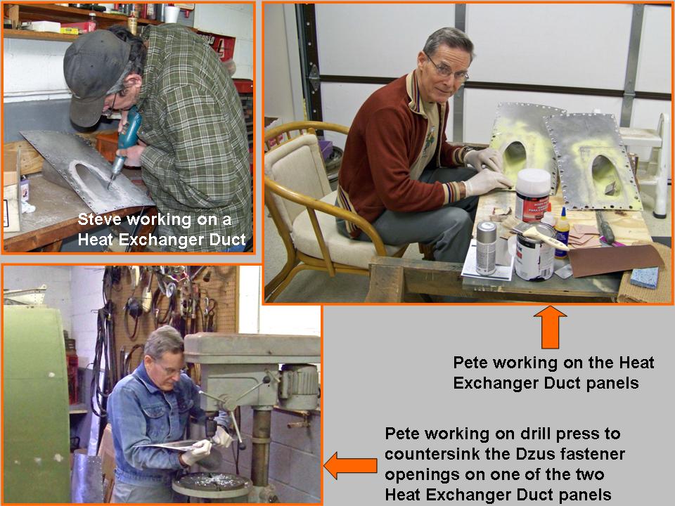 |
Installation 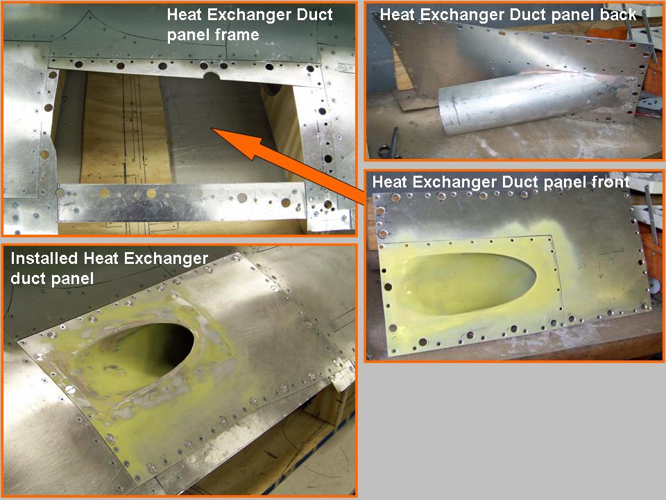 |
Completed panels 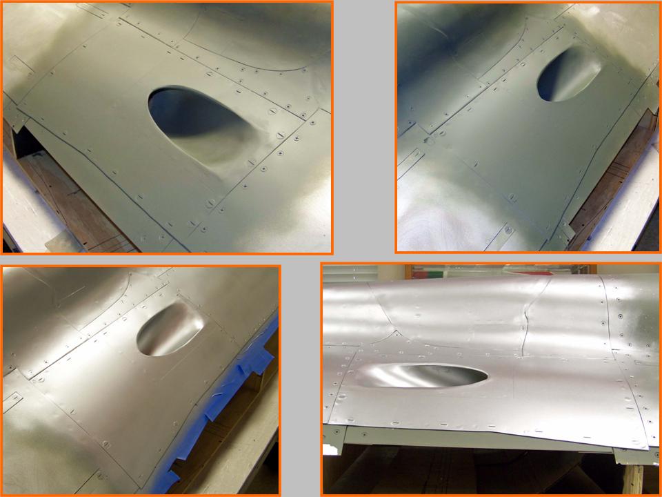 |
Note: In the original description of this HED panel, I used the label “RAT exhaust panel.” My source for that label was one of the many Hun books in my library. Pete Felts provided the following comments, which served to correct my misidentification.
Comments by Pete Felts: I fear I must correct you on what those ducts are for. If I'm not mistaken, they connect to the heat exchanger under the saddle. The RAT is a straight shot right from the intake. There is a door on the inside of the intake that opens when the RAT is actuated; the handle to open the RAT is located under the right canopy rail.
In contrast, the Heat, Vent, and Pressurization are maintained by the heat exchanger from the 16th stage of compression. Those ducts cool the air down to make it manageable. The heat exchanger looks like a big stainless steel box with a radiator attached to it.
I really don't know what the correct nomenclature of that panel would be, but I'm sure there is one. However, if I had to suggest a label, it would be Heat Exchanger Duct. This duct does not exhaust air. Instead, it is the source of fresh air that is used for pressurization and temperature control. The 16th stage of the compression supplies heated air to the Heat Exchanger to warm up the outside air, which is then vented through the bleed air valve on the left side of the airplane, back by the splitline.
Although the work on the spine section had been completed by the self-imposed deadline, the completion of the HED panel took much longer than expected. I had been side-tracked with the work on the aft fuselage section's frame work ... so the HED panel work had been on hold for a few months. But the main problem was finding a good way to make the HED, which turned out to be a major project by itself. Never mind ... progress is being made.
As the work on the spine section and the fuselage below it progresses, Steve and I will continue the work on the fuselage bottom panels. The Fuselage, Part 7 page will show how that part of the project is progressing.
As this major "modeling" project moves forward, I will post pictures of the progress we're making. I may not be able to have a real F-100 ... but a properly contructed full-scale model will not be distinguishable from the real thing. Stay tuned.
While the rebuilding and restoring efforts are important, please remember that the main focus of the F-100 project is its database. If you can supply stories and pictures that reflect your experience with the Hun, please do so. (You can click on the Contact me link to send me an email.) The objective is to develop a very comprehensive personal history of the Hun and of the people who flew and maintained her. You and the Hun deserve to be remembered in your own words.
If you want to return to the home page, you can either click on the
Home link shown here or by clicking on the Home link shown on left side of your screen. (You can also use any of the navigation bar links shown on the bottom of the screen to move around this website.)