|
Planning ... 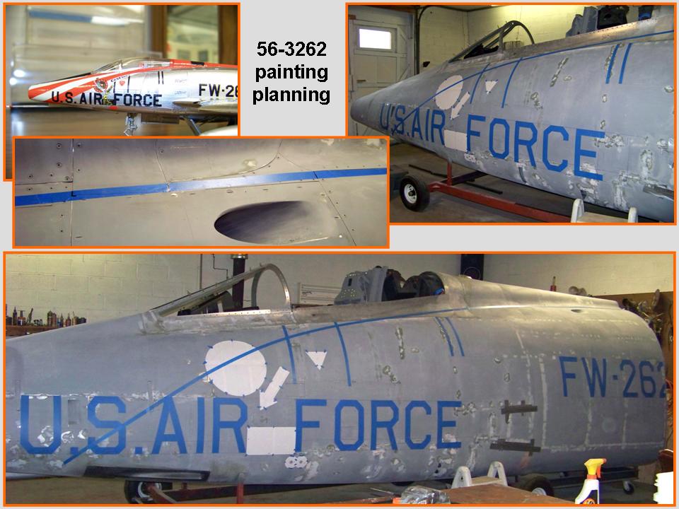 |
Templates ... 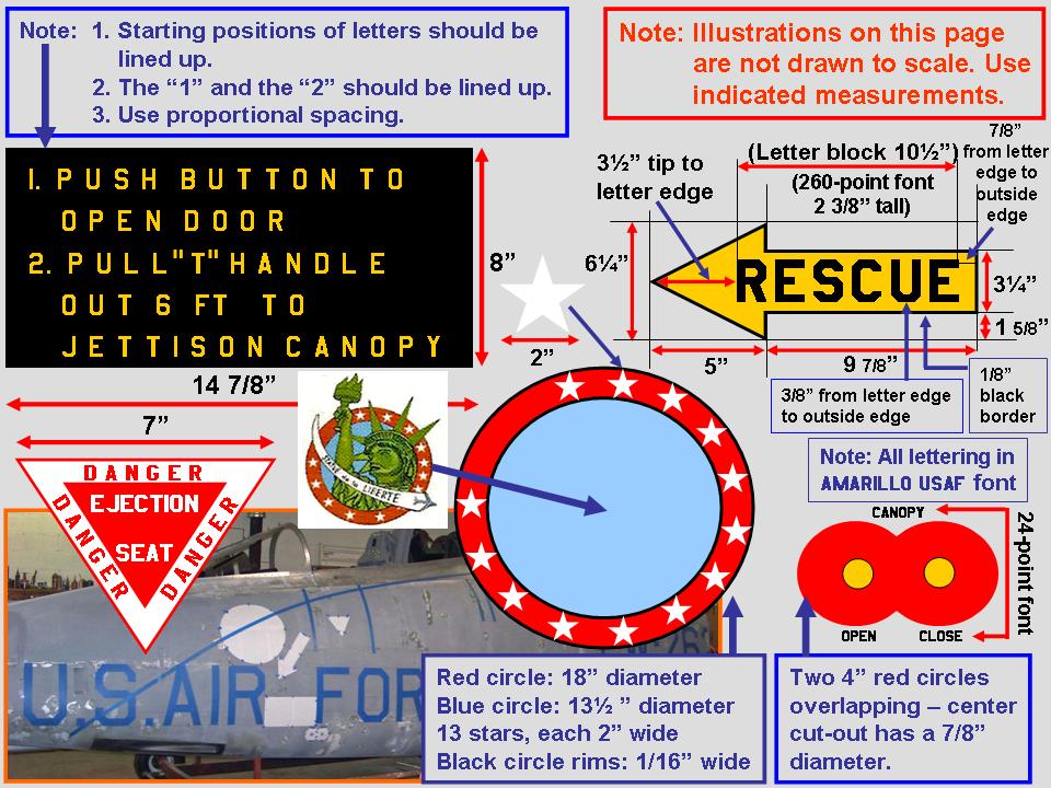 |
Lettering issue 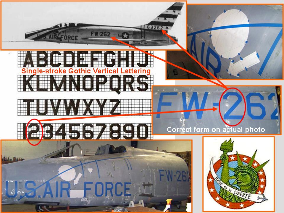 |
Fuselage, Part 10, documents the work done on the F-100D fuselage segment to make it ready for display in my F-100 "museum." Much of the remaining work centered on the final paint job. That paint job required a LOT of incredibly time-consuming planning ... not to mention the investment of time required to implement those plans.
Figure 1, Cell 01, shows what was involved in planning the paint job ... As you can tell by looking at the composite picture, I used a lot of blue painter's tape to help me block off all the lettering, templates, and color panels. (And, yes, the final painting will show black lettering ...) As you can tell by looking at this composite picture, the sanding has left a mottled-looking paint surface, but that flaw will be gone after one more application of primer-filler paint. One last round of (very "soft") sanding after that ... and then the final paint coats will go on. At this point -- it's 7 February, 2011 -- I'm just waiting for warmer weather before I start even thinking about that! (As I was treating myself to a coffee break at 3:30 p.m., the sleet was coming down so hard that I could hardly see the end of the driveway.)
Figure 1, cell 02 illustrates all the work that goes into planning the many fuselage templates. I started with a Powerpoint slide to do all the lay-out work. This slide was then saved as a .jpg file to let me insert the picture into this web page.
After I had posted Figure 1, cell 01, several visitors emailed messages about the apparent error in the number "2" format. (The official Air Force lettering specification shows a format different from the one I taped.) I used the actual format that shows up in the photos of this aircraft. Figure 1, cell 03 shows that my taped "2" format matches the "2" in the photo of 56-3262. In short, the planned paint job on my "model" matches that of the real aircraft.
Note: You can enlarge the pictures by clicking on them. Many of the pictures can be enlarged some more by placing the cursor on them and clicking again. Then maximize the window to get an even closer look.
|
Planning ... |
Templates ... |
Lettering issue |
Figure 2, cell 01 shows an even clearer picture of the "2" that was used on the actual aircraft. It's interesting that there are so many deviations -- some minor, some major -- from the "official" templates. That's why I tend to spend a lot of time looking at the pictures ...
Figure 2, cell 02 illustrates the preparation work that preceded the application of the final primer-filler coat. Before Steve started mixing the paint, Dave was completing the final sanding pass on the fuselage segment's bottom. As you can tell by looking at the picture, Dave didn't have a lot of room to work -- so he did an admirable "pretzel" routine to squeeze into some tight spaces. Putting the protective tape over the gun blast panels required similar gymnastics. (Applying tape to the back end of the two center blast panels required me to squeeze through the small spaces between the low trailer frame and the fuselage bottom. The picture shows the easier part -- taping the front portions of the outside panels. One of Steve's goats did the necessary supervising job ...)
Figure 2, cell 03 shows the final primer-filler spraying. Five straight days, starting on 14 February, 2011, finally let us complete the primer-filler paint work. After that paint coat cures, one last sanding pass with 400-grit paper will get the fuselage segment ready for the color coats. (But we'll first have to build a large paint booth ... spraying the color coats requires a lot more control over the temperature and the dust.)
Note: You can enlarge the pictures by clicking on them. Many of the pictures can be enlarged some more by placing the cursor on them and clicking again. Then maximize the window to get an even closer look.
|
About that "2"  |
Prep work ... 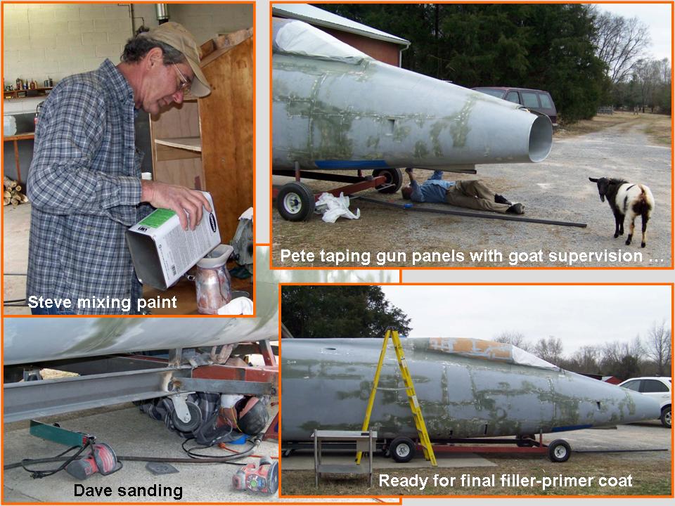 |
Primer-filler painting 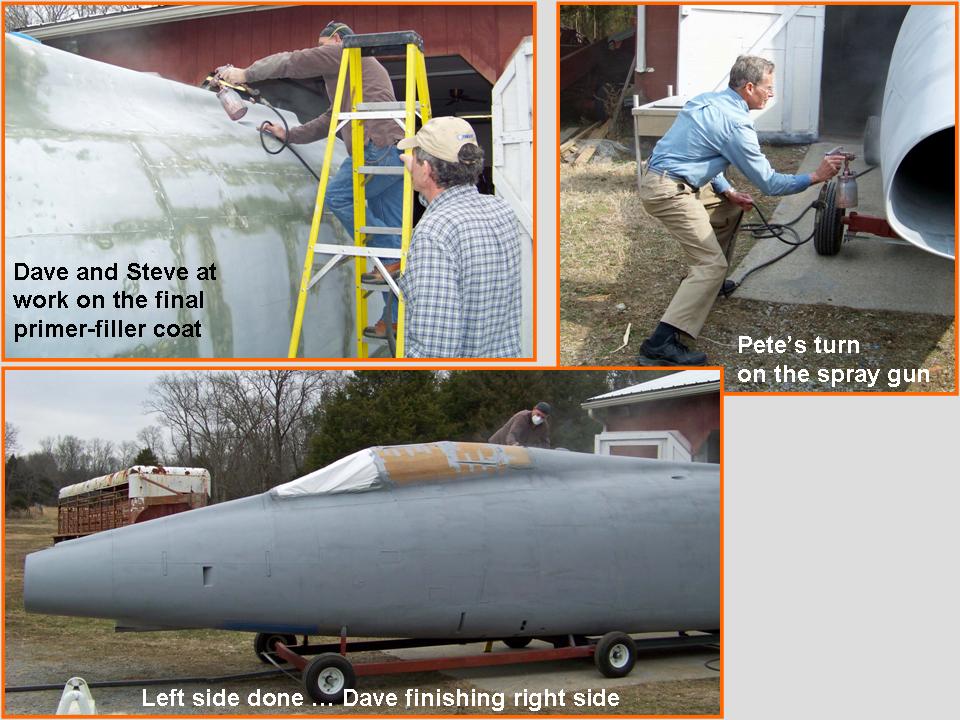 |
Note: You can enlarge the pictures by clicking on them. Many of the pictures can be enlarged some more by placing the cursor on them and clicking again. Then maximize the window to get an even closer look.
|
Final paint prep 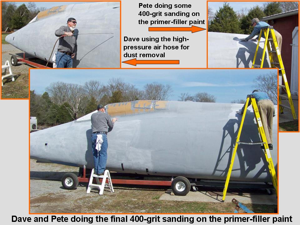 |
Paint booth 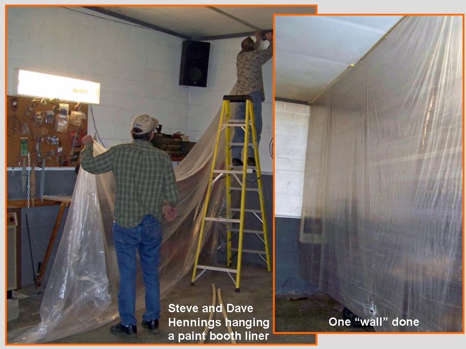 |
First finishing coat 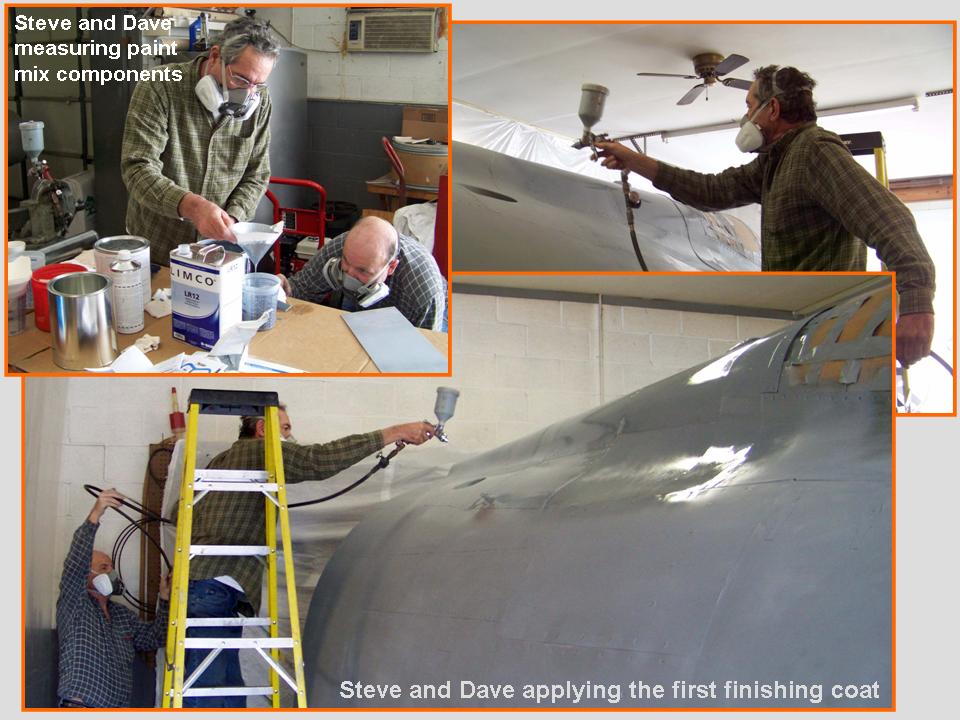 |
After the aluminum paint coat had been applied (very!) successfully, it was time to start work on the red and stripe white pattern. Because red shows up better over a white background, I began by taping the limits of the white area. The taping results are shown in Figure 4, cell 01. To make sure that the final striping matches the data -- pictures and descriptions -- perfectly, I spent a LOT of time studying the "detail" pictures you saw in Figure 1, cell 01. (Those pictures reflect many hours' worth of taping and retaping ...) A good paint job requires a good tape job ...
The composite picture in Figure 4, cell 02 shows the application of the white paint coat. Dave Graves and Steve Rettell are experienced painters, so their expertise eliminated guess work. Knowing how modern paints react under different temperature and humidity conditions is crucial, because such conditions define the paint mix with its hardener and reducer, as well as the spray gun nozzle opening and pressure. And then there's that knowledge of the precise nozzle distance from the surface to be painted and the rate at which the spray gun is moved. (I learned a lot about painting during this project!)
Figure 4, cell 3 shows what happens if you don't watch out where you're going. As I moved around the fuselage segment to check the tape adhesion, I didn't see the trailer wheel ... and managed to take a dive to the concrete. Steve and Dave were concerned that this senior citizen might have been damaged enough to require medical care and it took all my persuasive power to convince them that I was just fine. After the blood had been cleared off the floor and the bleeding had stopped -- and my face had been cleaned up -- Steve took a piece of cardboard on which he had written the number 6.5. He then requested that I hold up the sign so that he could take a picture ... then insisted that this picture HAD to be put on a web page. So here it is. (That 6.5 was my concrete dive score. Dave and I thought that, given the amount of blood I spilled, the score should have been at least an 8.5 -- but Steve is a tough grader ...)
Note: You can enlarge the pictures by clicking on them. Many of the pictures can be enlarged some more by placing the cursor on them and clicking again. Then maximize the window to get an even closer look.
|
Lots of taping 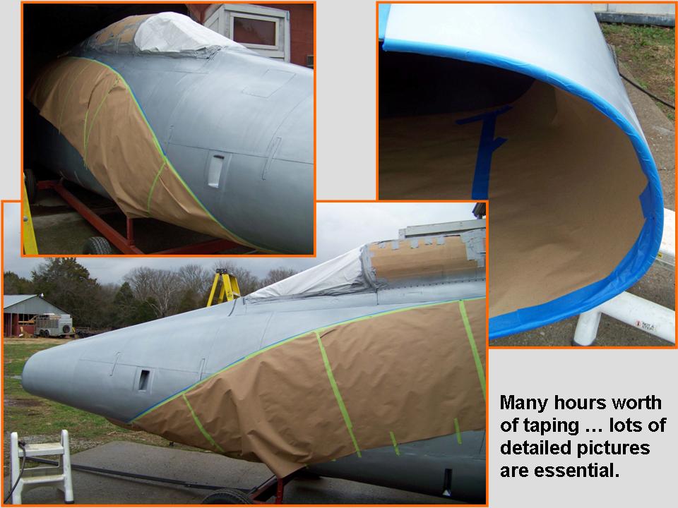 |
White paint work 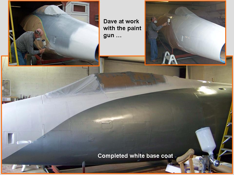 |
Paying the price 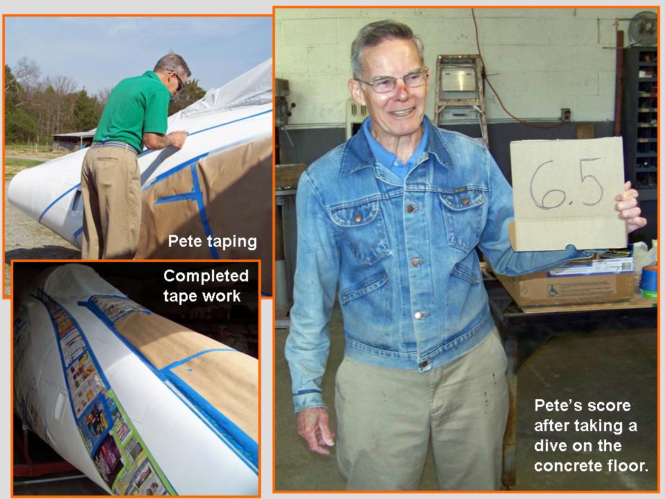 |
It's truly amazing how much time it takes to tape a design for a paint job. I had anticipated that I could complete the taping to delineate the red portions of the paint scheme in just a few hours. Instead, I spent well over 11 hours, spread across three days, to get the precise tape placement that I wanted. (And that does not include the hours spent looking at pictures and making multiple measurements.) And after the tape was properly applied, it still required additional hours to tape the paper over the areas that did not need red paint. (Fortunately, Dave and Steve managed to get the "papering" done, which was another roadblock on the way to the red paint work.) Finally, all the preparations were complete ... and then Dave and Steve mixed the red paint with the reducer and hardener to get the proper paint composition and consistency. The composite picture in Figure 5, cell 01, documents the process and the results.
In the meantime, I continued working on the badge and letter templates at home. Sketching the outlines of the Statue of Liberty head and arm was something I could manage ... but getting the shadows and dress folds right would take a real artist. Fortunately, I married such an artist 49+ years ago. Anne honed her talents at the Royal Academy of Fine Arts in the Hague, Netherlands, in the 1950s -- and she perfected her superb skills during the decades that followed. She can do it all ... whether it involves painting or making furniture. During the 1970s and 80s, she learned how to make jewelry ... and she has taken many university courses since to enhance her skills. (The sketches she makes of proposed designs are works of art in themselves.) Figure 5, cell 02, shows Anne at work ... and it showcases just two of her jewelry pieces.
Figure 5, cell 03, documents the final black and yellow paint work on the fuselage segment. I spent a lot of time looking at detailed photographs to make sure that the placement of the black lines -- and the black anti-glare panel -- would be correct. Because the panels were all traced from an original F-100D fuselage, rivets and screws provided perfect "markers."
Note: You can enlarge the pictures by clicking on them. Many of the pictures can be enlarged some more by placing the cursor on them and clicking again. Then maximize the window to get an even closer look.
|
Red paint work 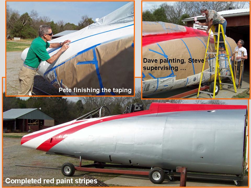 |
48TFW badge work 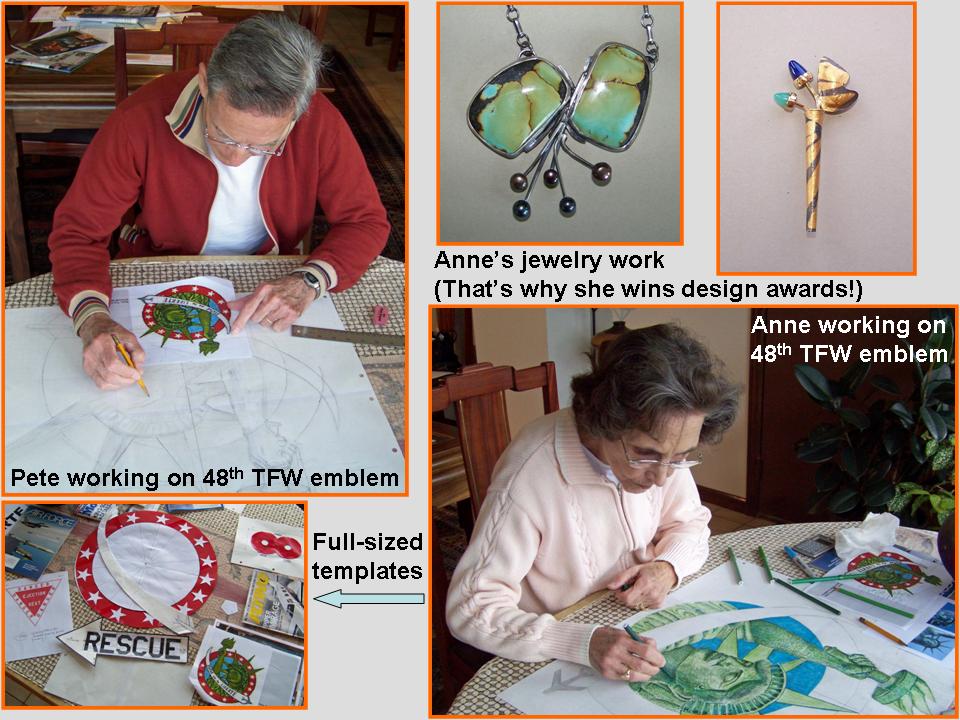 |
Final paint work 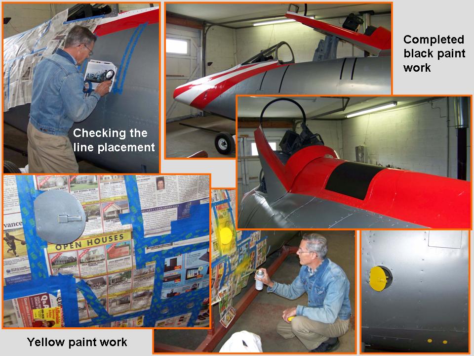 |
After completing the paint work -- except for minor touch-ups -- I had to shift my attention to the lettering and wing badge templates again. (Figure 1, cell 01 -- at the top of this page -- shows the initial (blue tape) placement of the lettering component.)
Figure 6, cell 01, documents additional template work. The pictures in the lower right corner shows the completed collection of paper lettering I cut and painted, as well as each letter's attachment to clear acetate. (I used the acetate sheets so that I could tape the letters in place to ensure their proper placement later.) The picture in the lower left corner shows the paper templates that I made to ensure the correct placement of the 48th TFW badge and the "streamer" that will display Col. Tolliver's name.
The most important two pictures in Figure 6, cell 01, are the ones in the upper left and right corners. Jack and Beth Harrell are the owners of Harrell Signs and Graphics, which produces stunningly gorgeous graphics arts designs. (Their business card is shown in the center of the composite picture.) Steve introduced me to Jack and Beth Harrell after I told him that I intended to tape and paint the letters and -- with Anne's help! -- the 48th TFW wing badge. After seeing some of the Harrell work on cars, trucks, and buildings, I was easily convinced that Jack and Beth would do absolutely flawless work while saving me a lot of time and aggravation. (You'll see the results of the Harrell magic later ...)
The composite picture in Figure 6, cell 02, tells the story of the broken nav light lens. (We broke it while moving the canopy frame to work on the -- electric -- open/close system. You'll see that work documented in Figure 6, cell 03 ...) Because this nav light was a REAL -- but never-used -- F-100 part, its destruction was a really sad event. Fortunately, when I told Tom Leatherwood that the original he'd sent me was broken during "construction" -- he mailed a new one free of charge. (And this one was even better that the first one I had bought!) It's a work of art. Steve and Dave happened to mention that they wouldn't mind having THAT hanging on the wall, so I called Tom and ordered three more lights. Tom charged $50 a piece for them, and that was very reasonable, given the fact that these things won't ever be produced again. Anyway, Steve, Dave, and I will have a nice memento to display. (Not to mention the fact that my Hun will have a brand-new nav light on its spine ...)
Figure 6, cell 03, documents the installation of the canopy open/close device. Steve and Dave had tried using a passive pneumatic system salvaged from the "back door" of a Minivan ... but that system didn't work as well as we had hoped. (For one thing, I don't want to use a lot of muscle power to open and close the canopy.) Back to the drawing board. Fortunately, Steve and Dave are superb (practical!) engineers ... so they devised a really first-class electrical system that lets me open and close the canopy at the touch of a button. (Yes, I can do that!)
Note: You can enlarge the pictures by clicking on them. Many of the pictures can be enlarged some more by placing the cursor on them and clicking again. Then maximize the window to get an even closer look.
|
Template work 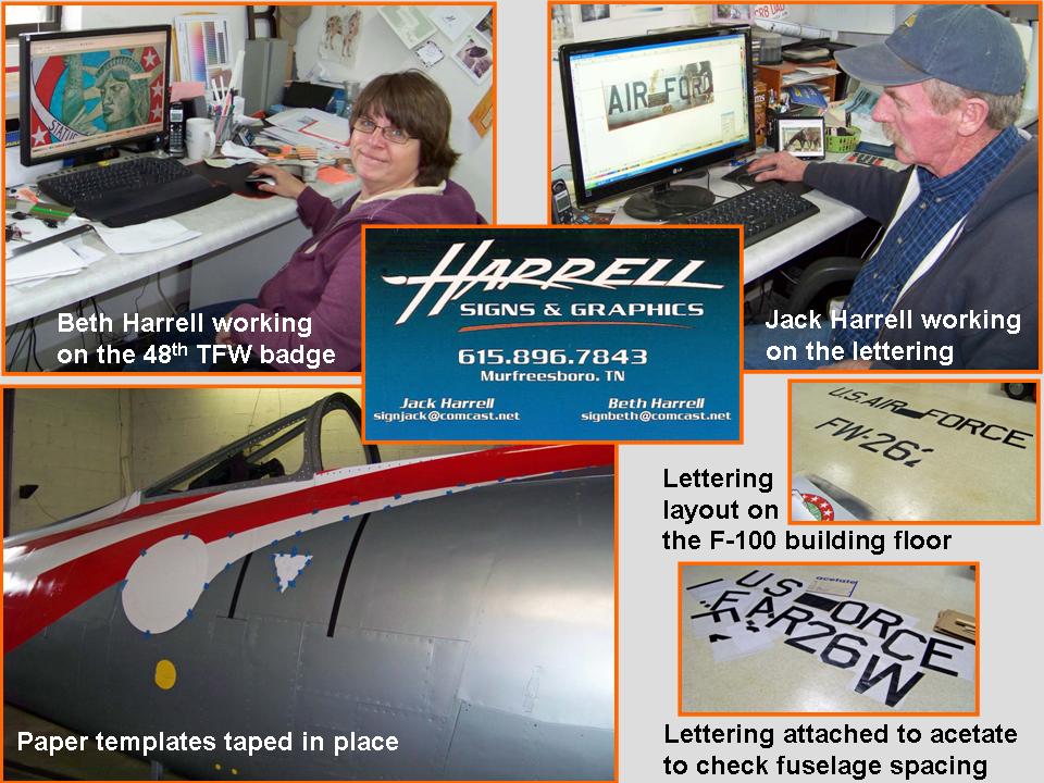 |
Nav light story  |
Canopy lifter 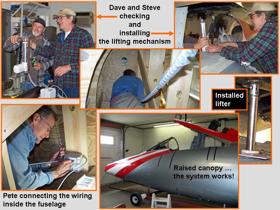 |
At this point in the project, the F-100 fuselage segment was essentially complete. Yes, there was a lot more work to be done ... for example, the windscreen components and the canopy "glass" still had to be installed. Not to mention that numerous instrument panel components still had to be put in place. Finally, all the lettering and the 48th TFW badge still had to be applied to the fuselage segment. But those tasks could be completed in the F-100 building -- my little museum! -- located across the driveway from my house. Besides, Steve needed his building back ... Fuselage, Part 11 documents how the fuselage segment was transported ... and it will show some of the "cosmetic" work that remained to be done. Check it out!
As this major "modeling" project moves forward, I will post pictures of the progress we're making. I may not be able to have a real F-100 ... but a properly constructed full-scale model will not be distinguishable from the real thing. Stay tuned.
While the rebuilding and restoring efforts are important, please remember that the main focus of the F-100 project is its database. If you can supply stories and pictures that reflect your experience with the Hun, please do so. (You can click on the Contact me link to send me an email.) The objective is to develop a very comprehensive personal history of the Hun and of the people who flew and maintained her. You and the Hun deserve to be remembered in your own words.
If you want to return to the home page, you can either click on the
Home link shown here or by clicking on the Home link shown on left side of your screen. (You can also use any of the navigation bar links shown on the bottom of the screen to move around this website.)