|
Loading 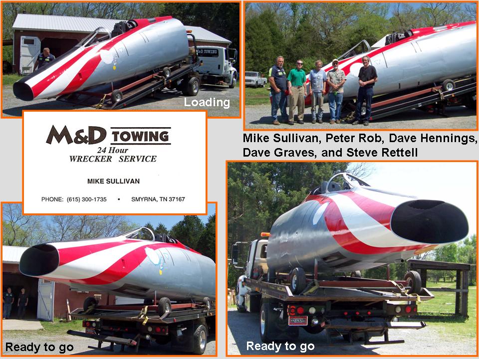 |
Arrival 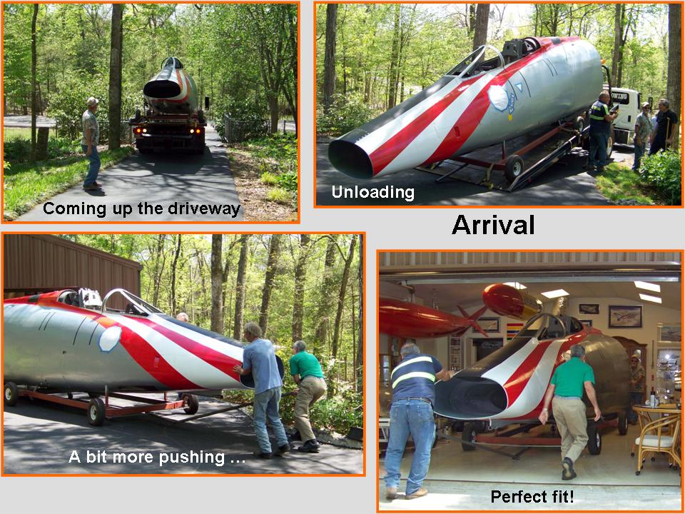 |
Into the building 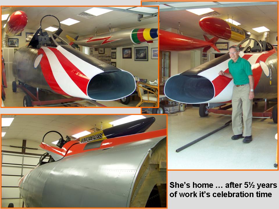 |
This web page documents the transportation of the fuselage segment from Steve Rettell's shop to my small F-100 "museum." It also illustrates the all-important "cosmetic" work -- such as the lettering and the application of the 48th TFW badge. Finally, you will see some of the work that still had to be done to complete the windscreen and the canopy.
The composite pictures in Figure 1 document the transportation process. Cell 01 shows the loading, cell 02 shows the arrival, and cell 3 shows the unloading and placement into the F-100 building. A big sigh of relief ... no problems and no damage! (Incidentally, the red stripes in the pictures show some scalloping -- that's due to the level of compression I have used in the pictures to make those picture files a bit smaller to facilitate the movement of those pictures to your screen. The actual paint is nice and solid red.)
Note: You can enlarge the pictures by clicking on them. Many of the pictures can be enlarged some more by placing the cursor on them and clicking again. Then maximize the window to get an even closer look.
|
Loading |
Arrival |
Into the building |
In the meantime, Jack and Beth Harrell continued to make the preparations to cut the vinyl lettering and 48th TFW badge "decals." The Harrell team spent most of 28 April, 2011, putting the vinyl decals on the fuselage segment. As I told Jack, even a beautiful woman looks better with make-up ... and the decals performed the same beautification function on my fuselage segment. Cells 01 through 03 in Figure 2 show why Jack and Beth have such a super reputation ... their attention to detail is simply phenomenal and excellence is their standard.
Given the spectacular finishing work that Jack and Beth did, it was very easy to take a LOT of pictures. Figure 2, cells 01 and 02, provide just some idea of the work and its results. Jack even taught me some of the basics of applying the decals. (Given the strong adhesive backing, it's necessary to apply a light mix of detergent and water on the decal's back and on the surface that the decal will be attached to. This technique will let you slide the decal into place and make some adjustments before you use a small squeegee tool to press the trapped water and air out. After the vinyl sets, a judicious application of heat will seal the vinyl to the surface.)
Note: You can enlarge the pictures by clicking on them. Many of the pictures can be enlarged some more by placing the cursor on them and clicking again. Then maximize the window to get an even closer look.
|
Harrell magic I 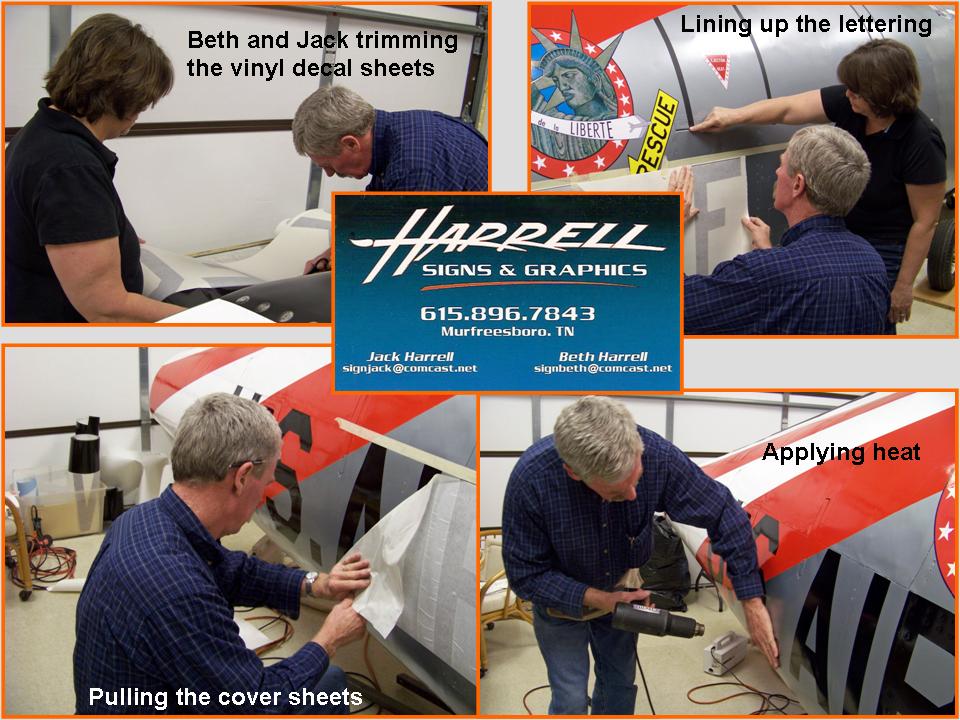 |
Harrell magic II 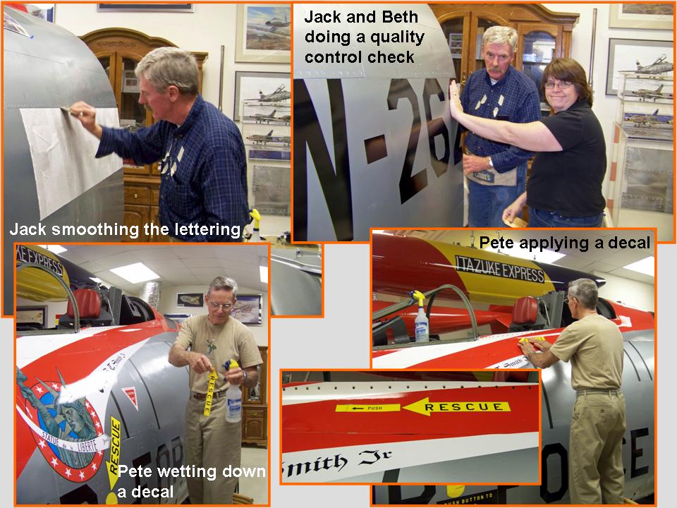 |
Harrell magic III 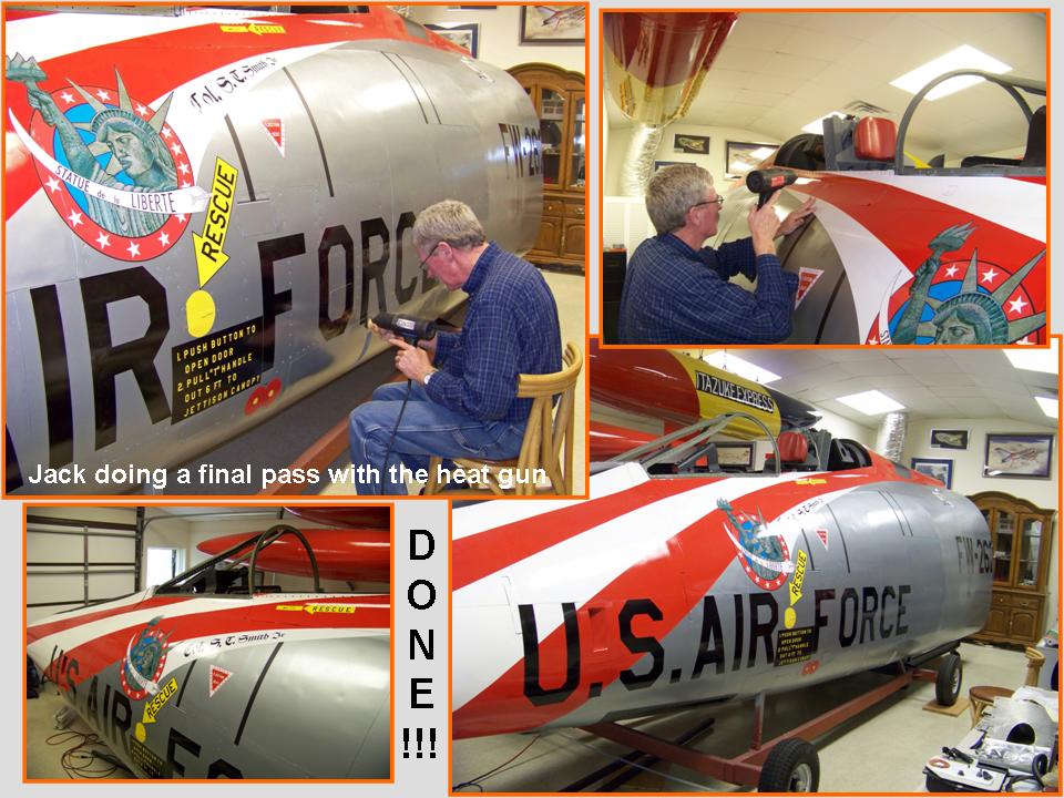 |
After Jack and Beth Harrell had completed their fuselage beautification work, it was was time to begin the work on the windscreen pieces. Fortunately, I did have the -- badly damaged -- original pieces, so those could be used as templates for new "glass."
The center panel consisted of four layers of glass, so the first job was to trace the original pieces and then cut those out of Lexan. Given the complex curvatures at the center piece top and the well-beveled edges, I was happy to let the Hamilton Glass Company in Murfreesboro do the cutting, shaping, and beveling. HGC had done an outstanding job cutting the instrument panel glass pieces, so I trusted them to do a superior job ... and HSG did an equally fine job on the windscreen center piece. I had already made the metal frame pieces, but I still had to fit the rubber "bed" pieces on which the panel would rest. Figure 3, cell 01, documents the work done on the center panel.
The windscreen side panels were, well, a mess. Therefore, the first order of business was to restore the curvature that had been compromised by glass breakage. Next, I placed paper over the restored pieces and then traced the outside edges of the repaired glass panels. The paper tracings became the source for the cardboard templates. After cutting the cardboard templates, I fit the cardboard over the repaired pieces and then saturated the cardboard with fiberglass resin to retain the shapes. Figure 3, cell 02, documents this phase of the side panel work. As you can tell by looking at the template picture, the side panels consist of two "sandwiched" pieces.
In the meantime, Steve and Dave discovered that the material that held the two windscreen panels in place against the frame would soften after the application of some heat. The three pictures along the top of the composite picture in Figure 3, cell 03, document the clean-up. The bottom three pictures show me tracing the paper template on a 1/8-inch Lexan panel, cutting the Lexan with a saw, and holding up the cut panel. (The larger inside panel was traced and cut the same way.)
Note: You can enlarge the pictures by clicking on them. Many of the pictures can be enlarged some more by placing the cursor on them and clicking again. Then maximize the window to get an even closer look.
|
Center panel work 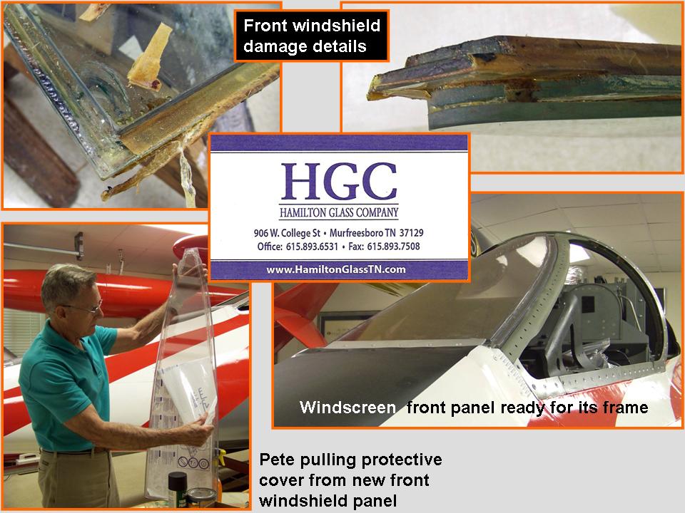 |
Side panel work  |
More side panel work 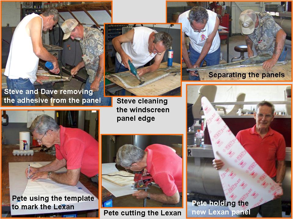 |
Some major tasks remain to be addressed at this point. For example, at this date (22 May, 2011), the windscreen side panels still have to be formed and the windscreen panels will have to be installed before I can insert the gun sight and the shroud instrument box. The canopy work has yet to be completed and the canopy will have to be installed. In addition, I'll have to complete the instrument side panels. Finally, there are those apparently inescapable little repairs and modifications that require attention. You'll see all of that work documented on the Fuselage, Part 12 web page.
As this major "modeling" project moves forward, I will post pictures of the progress we're making. I may not be able to have a real F-100 ... but a properly constructed full-scale model will not be distinguishable from the real thing. Stay tuned.
While the rebuilding and restoring efforts are important, please remember that the main focus of the F-100 project is its database. If you can supply stories and pictures that reflect your experience with the Hun, please do so. (You can click on the Contact me link to send me an email.) The objective is to develop a very comprehensive personal history of the Hun and of the people who flew and maintained her. You and the Hun deserve to be remembered in your own words.
If you want to return to the home page, you can either click on the
Home link shown here or by clicking on the Home link shown on left side of your screen. (You can also use any of the navigation bar links shown on the bottom of the screen to move around this website.)