|
Actuator tip modeling 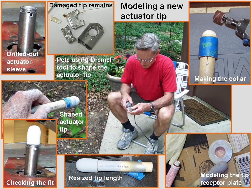 |
Actuator steel tip 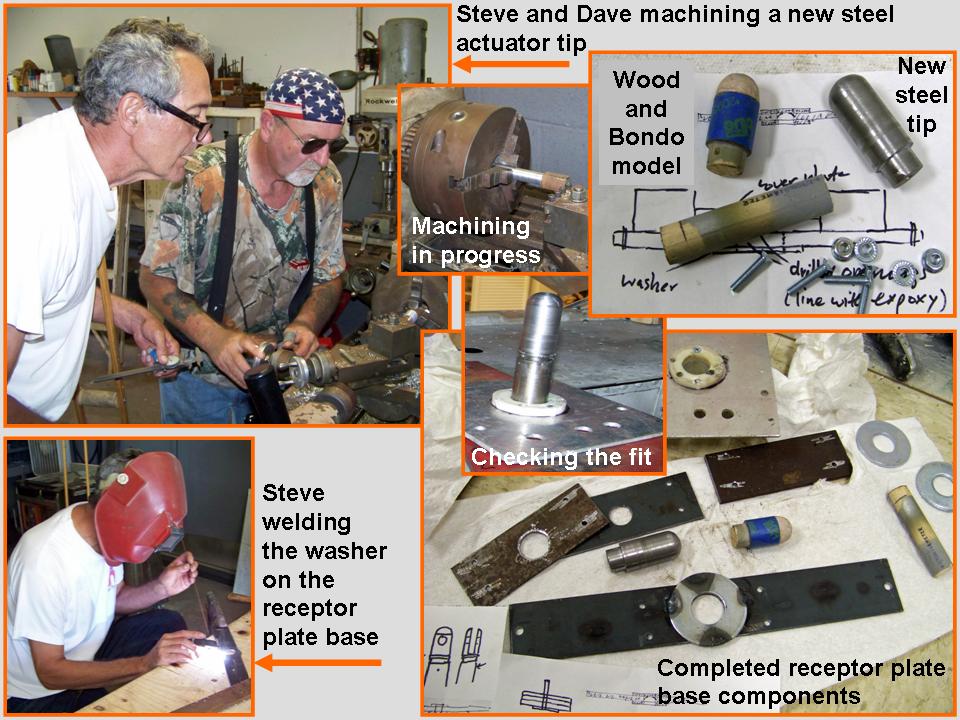 |
Completed modifications 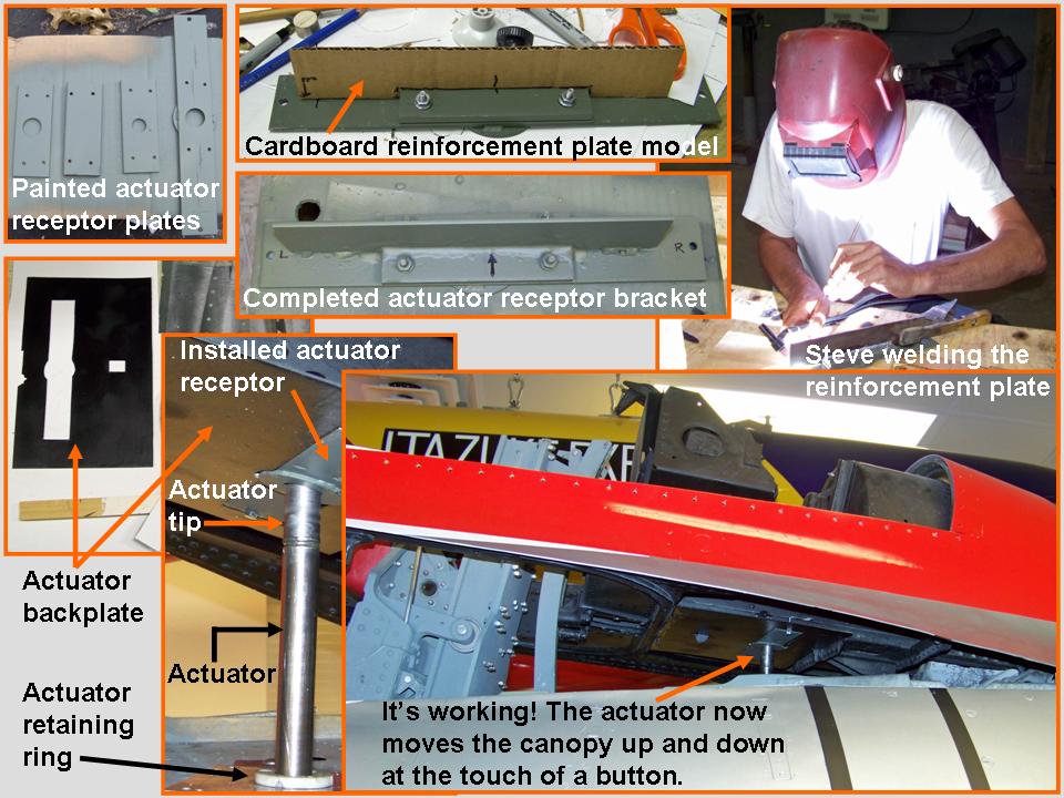 |
On the Fuselage, Part 11, web page I showed the transportation of the fuselage segment from Steve Rettell's work shop to my "mini-museum." I also illustrated the completion of the lettering and the application of the 48TFW "Statue de la Liberte" badge. In addition, you saw the new windshield and the work I did on the windscreen side panels. Finally, I documented the long-overdue completion and installation of the gear panel and the center pedestal.
As is often the case in a construction project, there is always the possibility that a "two steps forward, one step back" epsisode will occur. Sure enough, I forgot to unlatch the canopy before trying to raise it ... and that oversight did some damage. A quick inspection showed that the top of the actuator piston that raised and lowered the canopy was made of so-called pot metal, a rather brittle aluminum casting material ... which shears and/or fractures easily. Yep, sure enough, that's what happened. So I wound up spending almost four hours drilling out the piston top and cleaning up the piston. (Why the manufacturer of this equipment used pot metal at the maximum stress point is beyond me -- and why on earth didn't the designer use a simple screw thread so that this part could be removed and replaced easily?)
Given the problems with the actuator piston tip, it was clear to me that I should replace the fractured pot metal tip with a solid steel one. As I always do, I began by modeling the new tip. In this case, a small section of a wooden dowel stick became the basis for the new tip. (As you can see in Figure 1, cell 01, the dowel section was topped with Bondo that I shaped with the help of a Dremel tool.)
Also, after the original tip had fractured, Dave welded an additional large washer to the tip "receiver" to deepen the receiver hole to distribute the tip's side load across a larger area and to decrease the likelihood of slippage. Unfortunately, that additional washer eliminated the clearance between the canopy frame and the fuselage deck beneath the canopy. In turn, that lack of clearance caused the canopy to hang just short of its complete closing. Therefore, I redesigned the actuator receptor structure that held the piston tip in place as it moved the canopy. Steve and Dave converted my redesigned actuator receptor plate model to steel, thus eliminating the clearance problem. In the meantime, Steve and Dave used Steve's lathe to manufacture a solid steel actuator tip. Figure 1, cell 02 documents the work done by Steve and Dave.
You may have noticed that the steel actuator tip shown in cell 02 is longer than the model I made. That longer tip meant that I should be able to open the canopy to the level shown on all of the photos that displayed open canopies. After some initial testing, I discovered two things. First, the canopy moment arm in front of the actuator piston was slightly longer than I had originally measured, thus causing the canopy front to be lifted too high. Second, by eliminating one of the actuator receptor plates, we could cut even more off the actuator tip, thus yielding a more stable lifting point. Finally, my canopy raising/lowering tests revealed that the steel base plate buckled under the lifting load. Therefore, a stiffener had to be welded to the back of the actuator receptor. The results of these modifications are documented in Figure 1, cell 03.
Note: You can enlarge the pictures by clicking on them. Many of the pictures can be enlarged some more by placing the cursor on them and clicking again. Then maximize the window to get an even closer look.
|
Actuator tip modeling |
Actuator steel tip |
Completed modifications |
Making new windscreen panels turned out to be a major challenge when I discovered that the center windscreen panel that had been made -- see Fuselage, Part 11 -- did not fit the center frame indent. Trying to match the original plastic (?) frame "bed" turned out to be a near-impossible task. In addition, the thick (multiple) layers of Lexan, while nicely tranparent, yielded a greyish cast that did not match the "real deal." So it was back to square one -- $350 poorer.
As I started experimenting with 1/4-inch sheets of Lexan, I found out the hard way that I lacked the equipment to form the (still relatively-thick) Lexan sheet. After ruining several expensive sheets of polycarbonate, I decided to put this part of the constructon process on the back burner until I had found a way to fit plastic into the frame without having to build forms and then finding a large oven to shape the Lexan over that form.
The solution turned out to be simple enough. Lexan is rather flexible -- so I decided to use 1/8-inch Lexan to make it easier to bend the panels to the desired panel shape. However, because the original windscreen side panels were much thicker than their 1/8-inch thick Lexan counterparts, I had to make inserts to make the new side panels fit into the metal windscreen frames. That idea worked fine -- but only after I had spend some serious time on the learning curve, ruining several sheets of Lexan in the process. Never mind, I finally understood how the shape of a flat sheet changes when it is bent along a compound curve, thus enabling me to drill holes in the Lexan panel that would actually line up with the screw holes in the windscreen frame. Cell 01 in Figure 2 shows the successful completion of the left panel construction on 21 March, 2013 -- well over a year after the fuselage had been moved into my "museum". Cell 02 documents the right-side panel instalaltion and the center panel traces and initial fits. Cell 03 shows the center panel work and its completion on 11 April, 2013.
Note: You can enlarge the pictures by clicking on them. Many of the pictures can be enlarged some more by placing the cursor on them and clicking again. Then maximize the window to get an even closer look.
|
Left side panel work 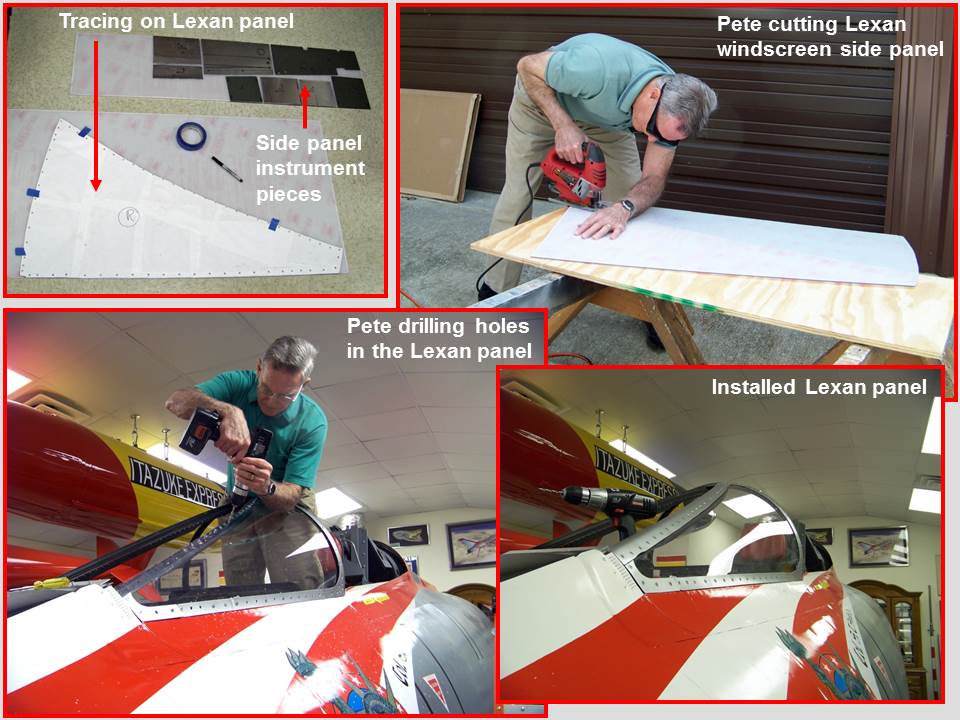 |
More panel work 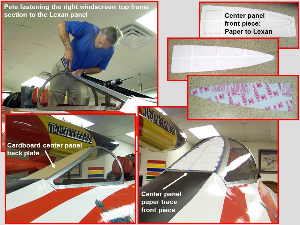 |
Center panel completion 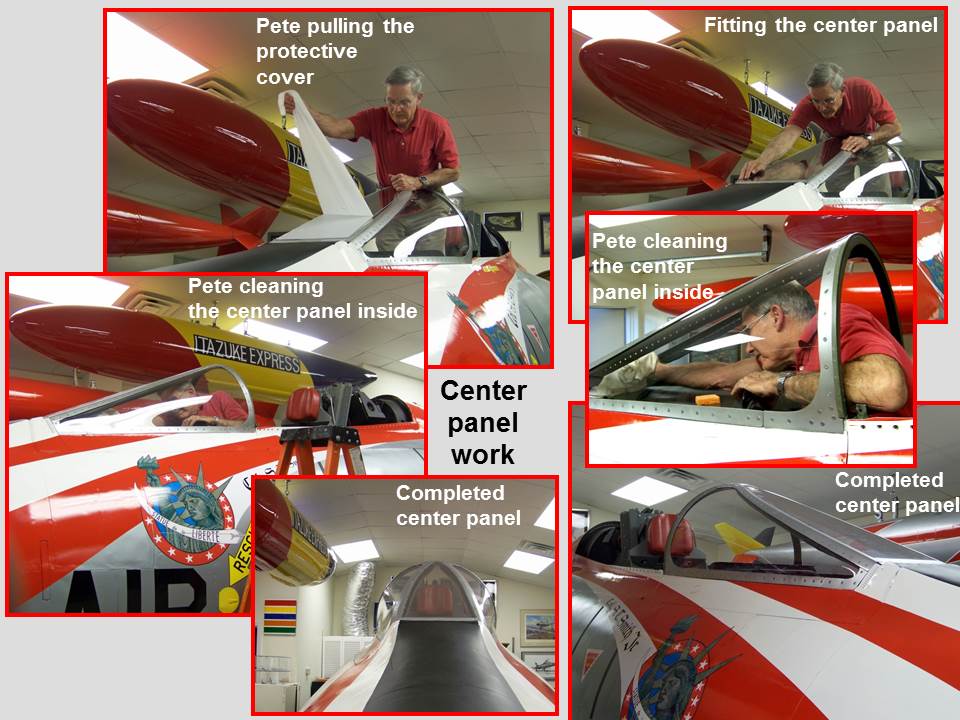 |
As this major "modeling" project moves forward, I will post pictures of the progress we're making. I may not be able to have a real F-100 ... but a properly constructed full-scale model will not be distinguishable from the real thing. Stay tuned.
While the rebuilding and restoring efforts are important, please remember that the main focus of the F-100 project is its database. If you can supply stories and pictures that reflect your experience with the Hun, please do so. (You can click on the Contact me link to send me an email.) The objective is to develop a very comprehensive personal history of the Hun and of the people who flew and maintained her. You and the Hun deserve to be remembered in your own words.
If you want to return to the home page, you can either click on the
Home link shown here or by clicking on the Home link shown on left side of your screen. (You can also use any of the navigation bar links shown on the bottom of the screen to move around this website.)