|
Initial fiberglass work 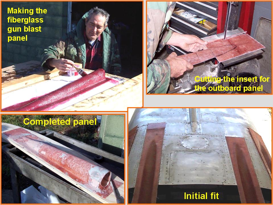 |
Completing the panels 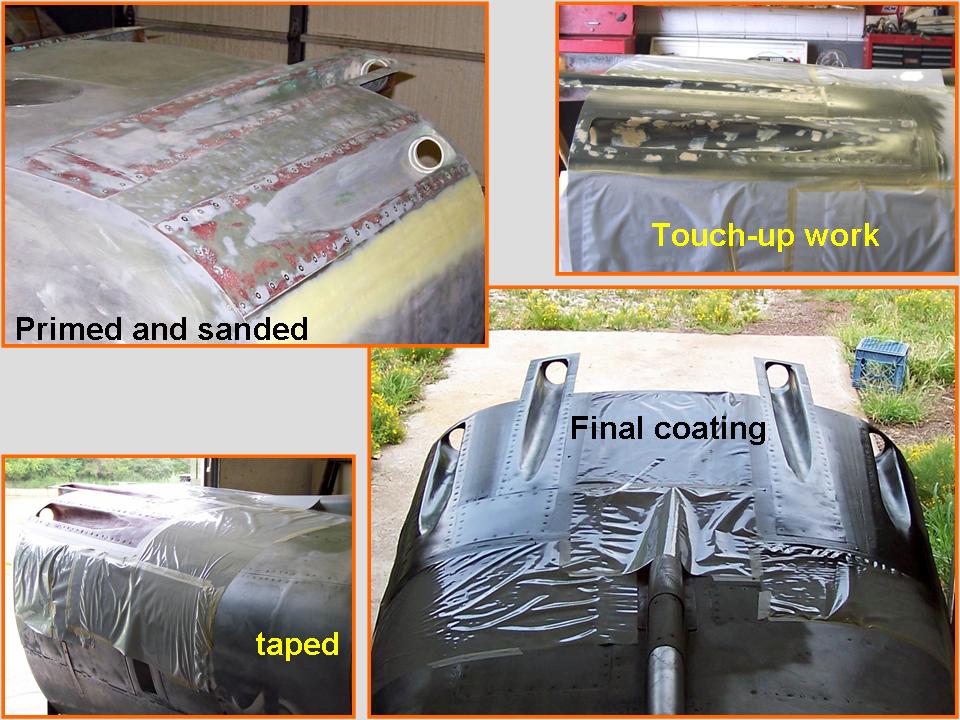 |
Doing it over 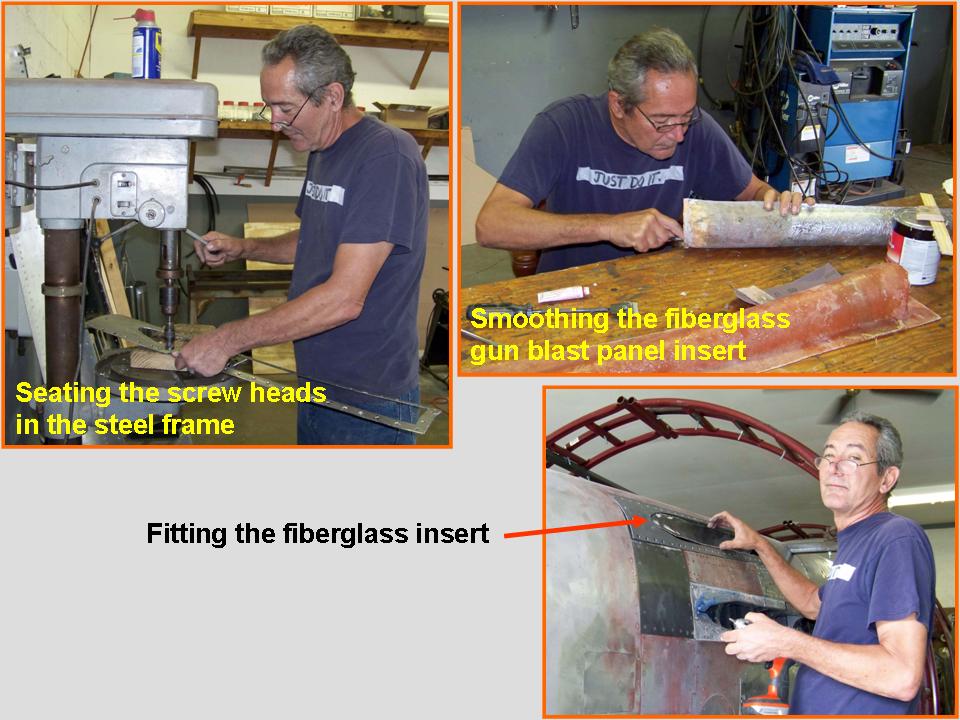 |
Given the complex compound curves of the gun blast panels, making them out of metal seemed to be more of a task than we could comfortable handle. We tried to farm out the manufacture of these panels, but we could not find any foundry or sheet metal shop that could do the job.
Given our lack of success in finding an "outside" solution, Steve Rettell -- an expert builder and a superb building techniques teacher -- suggested the use of fiberglass for several good reasons. First, the original gun blast panels are made from titanium and there is no reasonable way to either find titanium sheets or to work with titanium in the unlikely event that we could even find such material. Second, if we made the panels out of aluminum sheet, we would still have a really tough task in shaping the metal. Third, given the difficulties associated with metal forming of such a complex shape, fiberglass is a much more flexible material and Steve is a master at its use. In any case, whether we would use aluminum or fiberglass, we would wind up with an "artificial" material that would have to be textured and painted to match the "look and feel" of titanium. Fiberglass is a lot easier to work with in that respect, too.
Steve did express one concern: the gun blast panels are only 0.060" thick -- and a fiberglass version might be rather flexible. As I learned later, Steve called that game perfectly. When we were done, the thin fiberglass really looked good ... right up to the point where I started to tighten the Phillips head screws and discovered that the fiberglass edges dimpled and distorted. (Given their curved surfaces, the inside portions were sufficiently rigid.)
Figure 1 shows a series of pictures that begin to tell the story of how the gun blast panels were made -- from the initial fiberglass work to the start of a better solution. Cells 01 and 02 show the fiberglass work from start to finish. Cell 3 shows Steve's new approach ... which began with making a steel frame that would hold the usable center portions of the fiberglass cut-outs.
Note: You can enlarge the pictures by clicking on them. Many of the pictures can be enlarged some more by placing the cursor on them and clicking again. Then maximize the window to get an even closer look.
|
Initial fiberglass work |
Completing the panels |
Doing it over |
Figure 1, cell 03, illustrates the start of the new "manufacturing" process. First, the 0.060" steel sheet metal was cut to match the gun blast panel openings on the fuselage. Next, the fiberglass centers were cut from the original fiberglass panels, then Steve cut the steel panel centers out in order to fit these fiberglass cut-outs.
One problem remained: we could not let the steel frame overlap any portion of the fiberglass insert, since that would raise the steel frame above the fuselage's 0.060" aluminum skin panels. Therefore, there seemed to be no way to fuse the fiberglass and steel components. However, I had used the hard insulating foam you can buy in a pressurized can to serve as a backing for some other components, so Steve suggested that we use that same foam to create the perfect fit between the steel frame and the fiberglass insert.
Easier said than done, but Steve always comes up with a great solution. First, attach the steel frame to the fuselage. Second, spray the foam into the cavity behind the frame. Third, before the foam hardens, tape the fiberglass section tightly against the frame. The foam expands sufficiently to completely fill the cavity and makes a perfect fit against the fiberglass insert. The foam excess that is forced past the fiberglass/steel joint can be trimmed off when the foam has hardened, thus making a really smooth seam. In addition, the hard foam backing makes a really strong unit.
Figure 2 illustrates the just-described process. The upper left panel in Cell 01 shows the installed steel frame and the application of the foam by Steve Rettell. The upper right panel in Cell 01 shows Steve taping the fiberglass portion of the gun blast panel to ensure that the still-expanding foam behind it will fill the cavity behind the fiberglass and fix the fiberglass portion in place. The lower left panel in Cell 01 shows me (Peter Rob) spraying the sandable primer, while the lower right-hand panel shows two of the primed gun blast panels ready for sanding. Cell 02 shows me standing in front of the four installed, primed, sanded, and re-primed gun blast panels.
Figure 3, cell 03, shows the completed gun blast panels and the 20mm guns. (To see how those guns were modeled with PVC pipe, click on the "Guns" option when you get back to the Restoration Menu.) Note that, by the time we had installed the completed blast panels, the gun bay doors had been completed and the fuselage bottom had been painted in its final aluminum finish. To see how the gun bay doors were made, click on the "Fuselage (Part 7)" option when you get back to the Restoration Menu, then scroll down.
Note: You can enlarge the pictures by clicking on them. Many of the pictures can be enlarged some more by placing the cursor on them and clicking again. Then maximize the window to get an even closer look.
|
New process progress 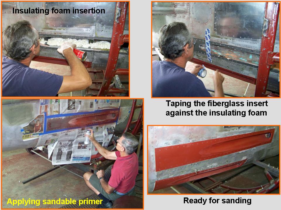 |
Installed and primed 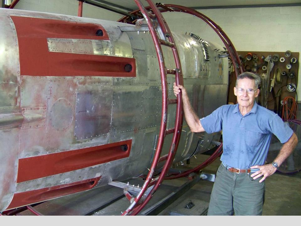 |
Completed! 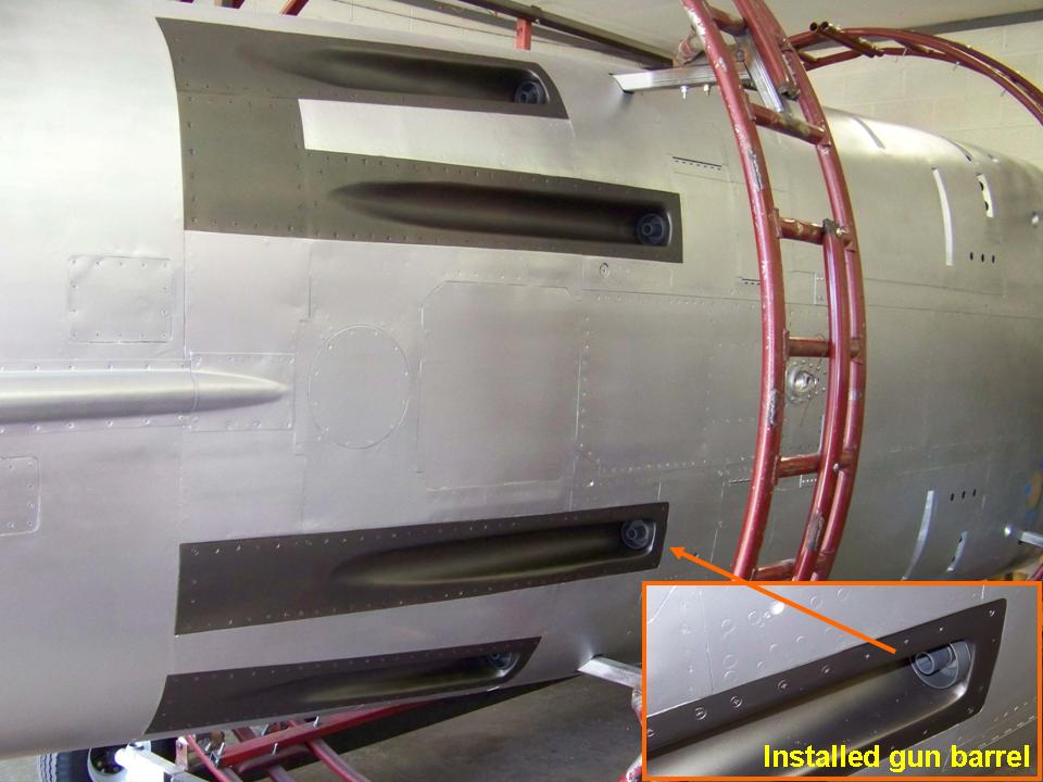 |
As this major "modeling" project moves forward, I will post pictures of the progress we're making. I may not be able to have a real F-100 ... but a properly contructed full-scale model will not be distinguishable from the real thing. Stay tuned.
While the rebuilding and restoring efforts are important, please remember that the main focus of the F-100 project is its database. If you can supply stories and pictures that reflect your experience with the Hun, please do so. (You can click on the Contact me link to send me an email.) The objective is to develop a very comprehensive personal history of the Hun and of the people who flew and maintained her. You and the Hun deserve to be remembered in your own words.
If you want to return to the home page, you can either click
on the
Home
link shown here or by
clicking on the
Home
link shown on the navigation bar on the left side of your screen.
(You can always use any of the navigation bar links to move around
this website.)